1396
Proceedings of the 18
th
International Conference on Soil Mechanics and Geotechnical Engineering, Paris 2013
foundation seismic forces by about 14% while the foundation
seismic displacements increased. Furthermore, the performance-
based soil-foundation-structure interaction analyses demonstrate
that the pile length can be shortened if increased displacements
and rotations of the foundation can be tolerated under the bridge
seismic and non-seismic performance criteria.
Figure 14. Transverse shear-displacement time history results for Pier
M5 using nonlinear inelastic soil springs (Yang, #2441).
In paper #2630, Chang assesses an existing pile foundation
through numerical models. He also suggests a new design by
checking up the maximum moment of the pile with the moment
capacities for the seismicity of interest. The pile displacements
correspondent to the moment capacities can be found and used
as the allowable pile displacements.
The work of Vintila et al. (paper #3031) investigates the
influence of seismic loads in foundation design for aeolian
units. It proposes optimal design and construction techniques
for different types of foundations on various soil profiles. The
parameters are determined in the field from geoeletric studies
and in the lab from oedometric as well as trixial tests. The
behaviour of shallow foundations may be improved by making
a skirt along the foundation edge. The foundation is thus
embedded in a rock of good quality and the active surface is
increases from 54% up to 70%. Large diameter piles connected
to a slab may also be used; it acts as a compensating box and
reduces the deformations. Finally, for thick loess layers (20m or
more), floating pile foundation may be chosen.
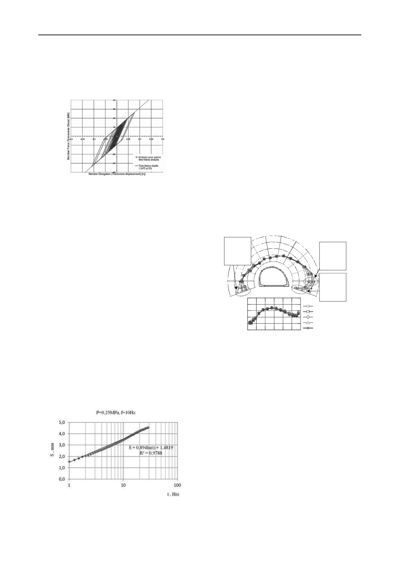
The effect of the loading history on soil-structure systems is
analysed by Taranov et al. with respect to the rheological
properties of the materials (paper #3065). They treat the integral
equations of the creep theory in an algebraic way considering
three different sequential processes: linear creeping of the
foundation, nonlinear creeping of the base soil and simultaneous
creeping of the soil and foundation. By using the Dynamic
Hereditary creep theory, they can estimate the foundations
settlements (logarithmical increase) due to machinery dynamic
loads. As displayed in Fig.15, data obtained from special
vibrostamp experimental tests allows to validate the theoretical
approach in order to describe the deformation progress with
time on steady-state phase of creep.
Figure 15. The curve of settlement progress with time a
z
=10µm
(Taranov et al., #3065).
9 NUMERICAL MODELLING
Four papers are mainly dedicated to numerical simulations even
though several other papers involve numerical modelling. In
this section, 3D FEM models are always considered.
Dynamic FEM analysis is carried out by Sawamura et al.
(#2299) to investigate the influence of spacing between multi-
arch culverts and its mechanical behaviour under seismic
conditions. In a previous study, dynamic centrifuge tests have
been carried out to confirm the difference of dynamic behaviour
due to the influence of spacing. Light fill material can be used
for the reduction of earth pressure during earthquakes. In the
present paper, 3D elasto-plastic FEM simulations are performed
for static as well as dynamic loads. For wide unit intervals, large
maximum bending moments are found. Figure 16 shows the
earth pressure distribution on the boundary portions of the
ground and arch culvert when maximum bending moment is
generated at right foot. When the arch culvert bends to the left,
as a result of seismic force, it turns out that a large earth
pressure acts on the right-hand side of arch culvert. Comparing
various spacings (from L=0.25H in red to L=1.5H in yellow),
the earth pressure becomes higher for larger unit intervals. This
could be due to the difference of horizontal displacements of the
soil around arch culvert as shown in Figure 16. On the other
hand, near the top part of the arch culvert, all cases lead to very
close results.
80
0
40
80
0
40
0
20
40
60
80
100
Case-1 : 49.1
Case-2 : 52.1
Case-3 : 58.3
Case-4 : 61.9
Single : 66.1
Case-1 : 26.9
Case-2 : 30.8
Case-3 : 38.5
Case-4 : 43.5
Single : 55.0
Case-1 : 12.1
Case-2 : 13.1
Case-3 : 17.8
Case-4 : 219
Single : 32.2
Case-1 (L=0.25H)
Case-2 (L=0.50H)
Case-3 (L=1.00H)
Case-4 (L=1.50H)
Case-single
Unit: kPa
Figure 16. Earth pressure distribution on the boundary portions of the
ground and arch culvert when maximum bending moment is generated
at right foot (Sawamura et al., #2299).
Since static and seismic earth pressures are often determined
from plan strain approaches, a 3D limit analysis numerical
approach is proposed by Santana et al. (#2846) to determine
seismic active horizontal earth pressure coefficients for vertical
rigid walls. In this work, an associated flow rule and perfectly
plastic behaviour are assumed. Various aspect ratios (b/h) are
considered for the wall and different friction angles for the soil
as well as soil-wall interface friction ratios. The applied loads
involve the soil weight and equivalent static forces directed
towards the wall, equal to
, where
is the seismic horizontal
coefficient (
=0, 0.1, 0.2, 0.3, 0.4 and 0.5). No vertical seismic
coefficient was considered.
As depicted in Fig.17, the mechanisms involved in the
mobilization of the active earth pressures are inferred from the
plastic deformation zones. The numerical results show a
significant three-dimensional effect of the b/h ratio: for small
values of this ratio, there is a significant decrease in the soil
seismic horizontal active earth pressure coefficients. For large
aspect ratios, the pressure coefficients are very close to the two-
dimensional case. The ratios between the 3D and 2D seismic
horizontal earth pressure coefficients are found to be
independent on the soil/wall friction ratio.


