1387
Technical Committee 202 /
Comité technique 202
1
2
c x
J dx
du
c
y
(8)
2
1
2
c xc x
J
u
c
y
(9)
Taking into account that
dx
du
, the unit tension in the
geosynthetic,
T
, can be obtained by replacing Equation (8) into
Equation (1):
c
y
Jc x
T
1
2
(10)
The constants
c
1
and
c
2
can be found using by two boundary
conditions. Assuming geosynthetic reinforcement confined with
aggregates, unit tension will be decreasing from one end to
another (Figure 4). Conventional solutions have used two force
boundary conditions at the two ends of the geosynthetic to solve
the governing differential equation. However, under small
displacement movements, these boundary conditions are not
realistic because the entire geosynthetic length is not mobilized.
In this study, and as presented in Figure 4, the geosynthetic
length includes two portions: an “active portion” which moves
under small displacement (i.e. portion AC in Figure 4), and a
“non-moving part” (i.e. portion BC in Figure 4).
T
y
Active Length=L'
Stationary Length
A
o
C
Figure 4. Boundary conditions differential segment of geosynthetic
In this study, two realistic boundary conditions are assumed
to solve the differential equation under small displacement. A
force boundary condition is assumed at Point A (
T
A
= T
0
), and a
displacement boundary condition is assumed at Point C (
u
c
= 0
).
Using these boundary conditions leads to unit tension and
displacement functions in the active length of geosynthetic
reinforcement. According to this solution unit tension in the
active length is related to the displacement of geosynthetic as
follows:
)()
4( )(
2
xu J
xT
y c
(11)
Since the confined stiffness of geosynthetic (
J
c
) and the yield
shear stress (
y
) are assumed constant for specific soil-
geosynthetic system for a given stress conditions, the multiplier
(
4J
c
y
) represents a key parameter in soil-geosynthetic
interaction under small displacements. This parameter is
defined as the “Stiffness of Soil-Geosynthetic Interaction” or
K
SGI
.
y c
SGI
J
K
4
(12)
Equations 11 and 12 establish a linear relationship between
the interface displacement (
) and the square of the unit
tension (
T(x)
2
) at any location within the active length (0 <
x
<
L
’
)
. The slope of this line is
K
SGI
. These equations also suggest
a parabolic relationship between
T
and
u
under small
displacement regime.
)(
xu
4 EXPERIMENTAL EVALUATION
As an illustration of the extensive program conducted to
validate the proposed model, the authors conducted a
conventional geosynthetic pullout test in a large pullout box
with internal dimensions of 1.5 m (60 inches) length, 0.6 m (24
inches) width and 0.3 m (12 inches) height. The test involved a
biaxial geosynthetic with dimensions of 300 x 600 mm. The fill
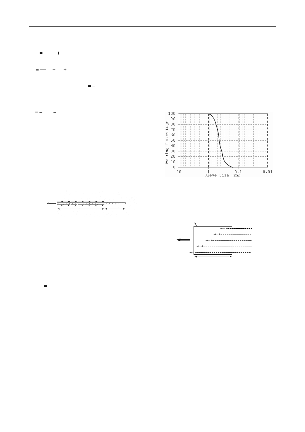
material used was clean poorly graded sand, which classifies as
SP in the unified system. The sand is composed of medium to
fine, and sub-angular to sub-rounded particles. The mean
particle size (
d
50
) is 0.44 and the coefficient of uniformity,
C
u
,
and the coefficient of curvature,
C
c
, are determined as 1.6 and
1.0, respectively. Figure 5 shows the gradation curve of this
soil.
Figure 5. Gradation of the fill material used in the pullout test
Telltale wire cables were used to connect 5 linear variable
differential transformers (LVDTs) to evenly spaced points along
the geosynthetic length in order to accurately measure
displacements of the geosynthetic during testing (Figure 6).
B
Pullout Force
(T
0
)
Geosynthetic Specimen
LVDT 5
LVDT 4
LVDT 3
LVDT 2
LVDT 1
L
u
5
u
3
u
2
u
4
u
1
Figure 6. Schematic of geosynthetic specimen and attached LVDTs
Results of the test are presented in Figures 7 and 8 up for the
initial portion of the test, up to a displacement of 1 mm. In
re 7, square unit tension of geogrid (
T
) is displayed versus
lacement ( ) for telltale locations of LVDTs 2, 3, and 4.
This figure illustrates good consistency of the results obtained
using at different locations (LVDTs 2, 3, and 4).
K
SGI
values are
obtained as 5.3, 7.9, and 8.6 (kN/m)
2
/mm. Figure 8 illustrates
the parabolic relationship between
Figu
disp
u
T
and .
u
5 SUMMARY AND CONCLUSIONS
Most of the parameters used in the design of geosynthetic
reinforced systems consider characterization of the ultimate
failure, and typically using unconfined conditions. However, the
actual performance of pavement reinforced systems governs by
the interaction between surrounding soil and the geogrid in
small displacement conditions. In this study, a new parameter,
defined as “Stiffness of Soil-Geosynthetic Interaction” or
K
SGI
,
was introduced to address soil-geosynthetic interaction behavior
under small displacements.
K
SGI
combines the interface shear
properties of the reinforced system with the load-strain
properties of geosynthetic under confined conditions.


