1386
Proceedings of the 18
th
International Conference on Soil Mechanics and Geotechnical Engineering, Paris 2013
the results obtained suing a conventional pullout test setup
conducted for validation of the model.
2 ASSUMPTIONS OF THE SOIL-GEOSYNTHETIC
INTERACTION MODEL
The proposed model is based on two major assumptions. The
first assumption concerns the Unit Tension - Strain relationship
of geosynthetic products. Researchers have assumed different
relationship between the unit tension in geosynthetics (T) and
strain (
). While Wilson-Fahmy et al. 1994 assumed a linear
relationship between T and
, Perkins and Cuelho, 1999 used a
nonlinear relationship, and Ochiai et al. 1996 and Sieira et al.
2009 assumed it to be equal to unconfined stiffness of the
geosynthetic obtained from the in-isolation wide-width tensile
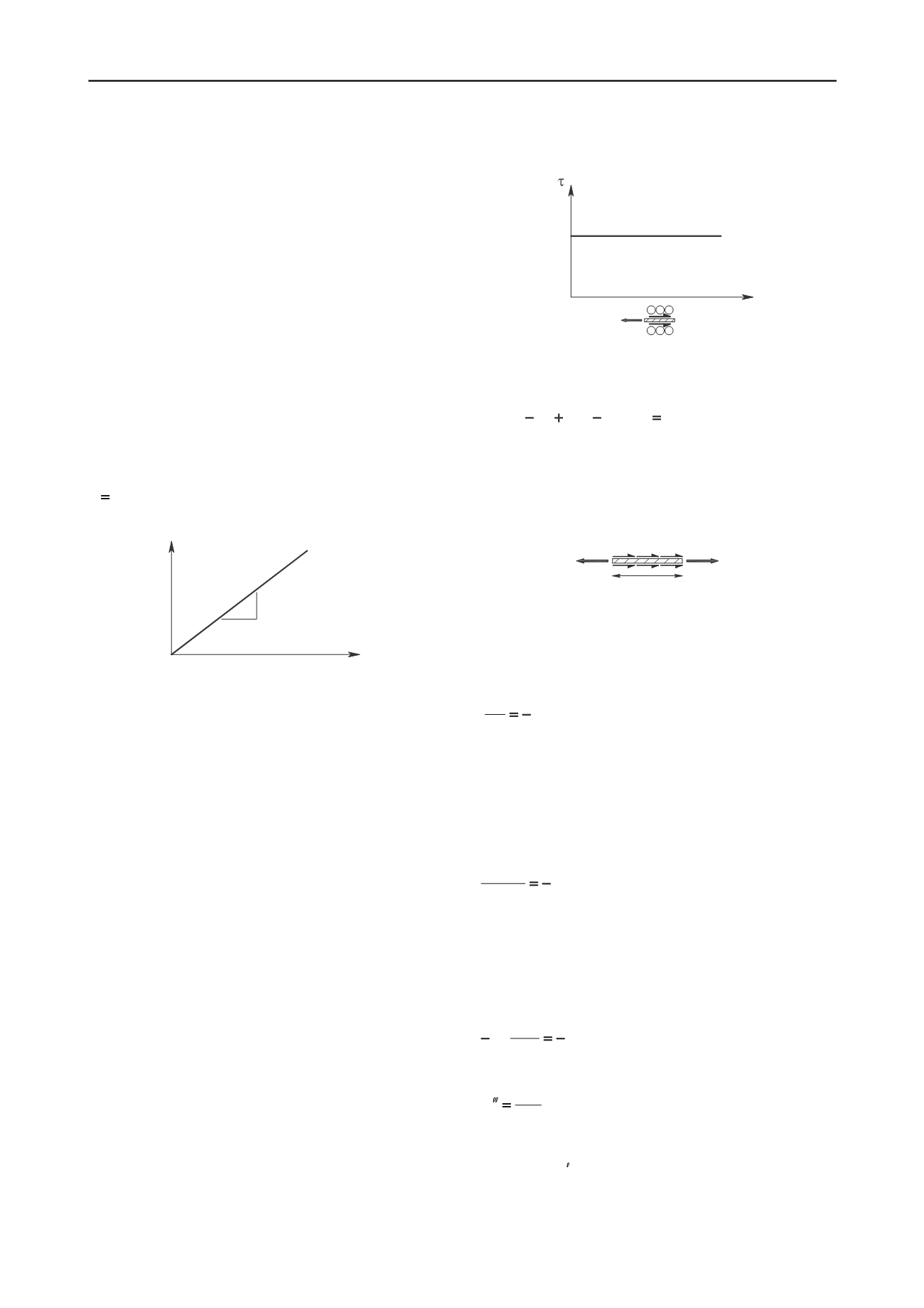
test. For the purpose of this study, it is assumed that the
T-
relationship of geosynthetic materials remains linear under soil
confinement. However, the slope of this line would be not
necessarily the same as (probably higher than) in the unconfined
condition. As shown in Figure 1, the slope of
T-
line (
J
c
or
Confined Stiffness of Geosynthetic ) is assumed constant for
small displacement:
c
J T
(1)
T
J
(kN/m)
c
Figure 1. Tensile load-strain relationship for geosynthetic
reinforcement under confinement
The second assumption addresses the relationship between
soil-geosynthetics interface shear and the displacement of the
geosynthetic, which is also known as interaction law. Various
assumptions for the distribution of interface shear have been
adopted in previous studies. For example, Sobhi and Wu, 1996
assumed a constant interface shear, while Abdelouhab et al.,
2008 considered linear distribution of interface shear. In
addition, a bi-linear distribution was used by Juran and Chen
1988 and Madhav et al. 1998, other non-linear distribution were
used by Perkins and Cuelho, 1999, and an hyperbolic interface
shear relationship was assumed by Gurung and Iwao, 1998.
Sugimoto and Alagiyawanna (2003) showed that the direct
evaluation of the interface properties from the ultimate state
may not be appropriate to simulate the actual geosynthetic
behavior in reinforced soil masses before failure in a pullout
test. Sobhi and Wu (1996) defined the limit shear stress for
pullout test, which was lower than the maximum shear stress
and a function of overburden pressure applied to the soil-
geosynthetic interface. They showed results from finite element
analyses indicating the development of uniform shear stress
independent of the frontal pullout force magnitude and length of
the geosynthetic. In the study presented in this paper, a uniform
distribution of interface shear is assumed over the active length
of the reinforcement, as shown in Figure 2. The constant
interface shear stress is defined as the yield shear stress (
y
),
which is independent of the interface displacement at any point
along the confined active length of geosynthetic.
3 FORMULATION
The model assumptions are considered in order to solve the
governing differential equation of a confined geosynthetic. The
solution can be used to obtain the displacement, strain and force
at any point x along the length of the geosynthetic.
u
y
u
Figure 2. Interface shear-displacement relationship
As shown in Figure 3, the force equilibrium of a differential
segment of the confined geosynthetic can be written as:
0 )
2( )
( )(
dx
dT T T
(3)
Where:
ic
geosynthet
the and soil
between
shear
Interface
ic
geosynthet
the in
tension
Unit
T
ic
geosynthet
the of
segment
al
differenti
A dx
:
:
:
T
T+dT
dx
y
Figure 3. Force equilibrium for a differential segment of geosynthetic
Rearranging this equation returns the force equilibrium
differential equation governing soil-geosynthetic interaction:
2
dx
dT
(4)
According to the second assumption described in the
previous section, the soil-geosynthetic interface shear is
constant along the active length of the geosynthetic (i.e.
=
y
).
Also, using confined stiffness of geosynthetic system (
J
c
), the
unit tension (
T
) can be replaced using Equation (1). Substituting
accordingly into Equation (4) returns the following equation:
y
c
dx
Jd
2 ) (
(5)
The axial strain in the geosynthetic can be replaced by the
derivative of displacement. In addition,
J
c
is considered
constant for a given normal pressure and under small
displacements. Therefore, Equation (5) can be rewritten as
follows:
y
c
xd
ud J
2
2
2
(6)
where
u
is the interface displacement. Equivalently:
c
y
J
u
2
(7)
Integrating twice the differential Equation (7), returns
equations for
u
and , respectively:
u


