1397
Technical Committee 203 /
Comité technique 203
'=2/3;
=0
'=2/3;
=0.2
'=2/3;
=0.4
Figure 17. Plastic deformation zones for a friction angle
’=30º, a soil-
wall interface friction ratio
’=2/3, and three values of the seismic
coefficient
– 0, 0.2 and 0.4 (Santana et al., #2846).
The 3D response of a suspension bridge anchor block to
oblique-slip fault movement is modelled by Avar et al. (#3052)
using the FEM. The bridge project is located in Izmit Bay
(Turkey) where secondary fault systems were evidenced. The
lateral and vertical fault displacements are applied at the base of
the soil medium (100m deep). The constitutive model adopted
is the elasto-plastic model with standard Mohr-Coulomb (MC)
yield surface formulation. As the fault propagation through
saturated fine-grained soil deposits occurs too fast for excess
pore water pressures to dissipate, the analysis has been
performed using effective parameters for strength and stiffness
in the clay layers. The fault displacements result in the rotation
and translation of the anchor block. Figure 18 compares the u
x
displacement at the ground surface for the free field and the
anchor block-soil models along a line in the x-direction passing
through the centre of the soil-anchor block. The difference
between free-field and the anchor block-soil model
displacements at the anchor block boundaries are significant.
The discontinuity in vertical downward movement in the
vicinity of the right hand side (footwall side) of the block
implies separation between the soil and the block developing.
The anchor block also moves 250 mm in the x-direction
following the movement of the hanging wall (Fig. 18). The rigid
movement of the anchor block is clearly observed in Fig. 18. It
is evident that the rigid anchor block introduces a kinematic
constraint to the propagating fault. The ground moves slightly
towards positive x-direction in the footwall side in the free-field
model as seen in Fig. 18 whereas this does not occur when the
anchor block is placed.
‐300
‐250
‐200
‐150
‐100
‐50
0
50
100
‐250
‐150
‐50
50
150
250
ux (m)
x‐coordinates (m)
Free-field
soil-anchorblock
model
Figure 18. Horizontal displacements, u
x
, in the x-direction along the
centre of the model at the ground level (Avar et al., #3052).
The dynamic behaviour of a 3D “soil-foundation-building”
system with a seismic isolation is investigated by Boykov et al.
(#3064). The structure is a real multi-story building, located on
a landslide slope in the seismically-active area of the Crimean
Republic. The soil base is represented by a talus layer about 10-
18 m deep with a shifted mudstone layer (about 3-5 m deep) and
an argilite foundation below that. The initial building design
called for drilling piles (
=620mm, L=35mm), embedded into
the argilite bedrock. The 3D FEM model involve absorbing
boundaries and 3C synthetic accelerograms are considered. A
non-associative law (modified Mises-Schleicher-Botkin’s
criterion) is chosen for the soil. Rayleigh damping is also
included in the model.
The specification of the work of soil and damper lead to an
increase of shifts in the plane of the building. Maximum
amplitude increases from 8 to 10 cm. At the maximum
amplitude, the shifts are mainly oriented along the action of the
radial component of the seismic load. The oscillations in the
horizontal plane are thus close to the neutral situation. That is
why the building does not have tendencies to horizontal shifts.
The consideration of the plastic work of the damping layer
allows the calculation of the amplitude decreasing of the
oscillations of the top floors of the building. As displayed in
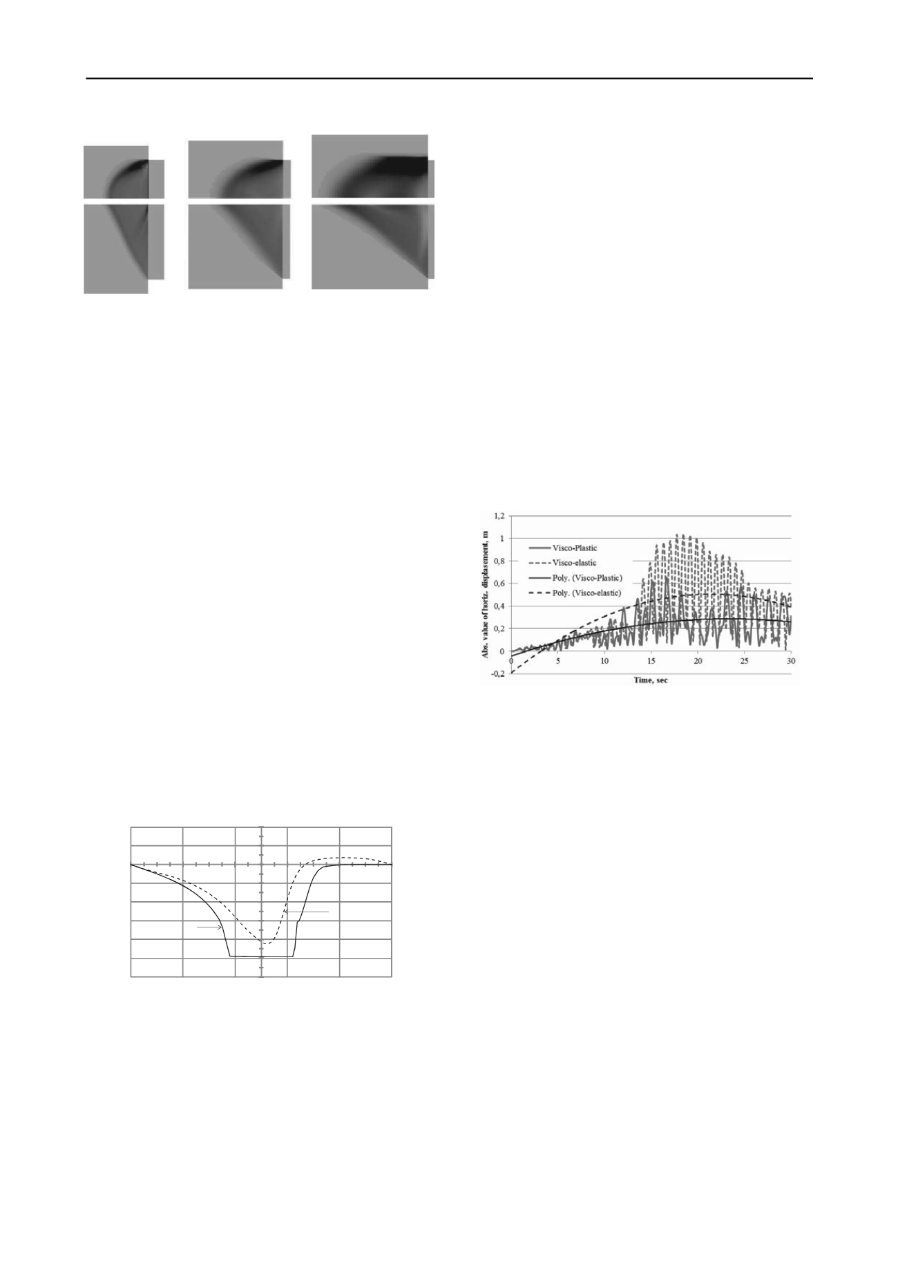
Fig. 19, the maximum values of these shifts significantly
depend on the constitutive law and they approximately reach
64 cm in the period of time from 15.1 to 24.5 seconds. The
process of irreversible building settlement develops to 20 s of
load, after which the settlement becomes stable and exceeds at
least the value of 13 cm. Finally, due to inertial forces in the
soil, areas of significant tensile forces may appear in the piles.
These zones are located below the pile heads and must be taken
into account when designing grillage for the structure. This
work also shows that the utilization of piles during seismic
loads in layered soils with various deformation properties leads
to the appearance of forces within these piles that can exceed
the forces at the pile heads by as much as a factor of two.
Figure 19. The diagram of absolute value of displacements for upper
foundation slab (visco-elastoplastic model) and grillage slab (visco-
elastic model), Boykov et al. #3064.
10 DISCUSSION AND CONCLUSION
This session is mainly dedicated to the seismic response and
stability of soils, foundations and geotechnical structures. The
various sub-topics lead to the main following results:
Site effects and soil seismic response
: 1D-3 components
simulations allow the analysis of strong seismic motion for
the Tohoku quake; for the site of Bam (Iran), some
discrepancy is found between the expected amplifications
(from EC8 soil types) and actual amplifications; very soft
sites may strongly amplify the seismic motion in urban areas.
Landslides
: through shaking table tests, a critical direction of
the seismic loadings is evidenced.
In situ tests
: penetrometric tests characterize the relative
density of soils (but difficult for moisture content);
pseudostatic tests on piles allow load increments.
Soil behaviour and liquefaction
: Prevost’s model simulates
well pore pressure and plastic strain accumulation; response-
envelopes method assesses to sensitivity to mean pressure
and stress induced anisotropy.
Earth works stability
: yield design allows the analysis of the
stability of retaining walls even if water pressures are
included; exces spore water pressure may be reduced by
geosynthetics; probabilistic approaches assess the influence
of the spatial variability of soil parameters on stability;
recommandations are made on evaluating seismically
induced deviatoric displacements for earthen levees.
Soil improvement
: using stiff columns, a large replacement
area is mandatory to mitigate liquefaction; depending on the


