1393
Technical Committee 203 /
Comité technique 203
It seems that most of the load is taken by the shaft and only
900 kN are taken by the tip at the maximum load of the test
performed. The behaviour of pile-soil systems corresponds to a
quasi elastic phase with little plastic deformations. The main
advantages of the proposed pseudostatic tests is the possibility
to apply load increments.
4 SOIL BEHAVIOUR/LIQUEFACTION
The possibilities of the Prevost’s model are highlighted by
Cerfontaine et al. (paper #1759) and compared to that of a
classical Drucker-Prager model. The Prevost’s model is able to
capture the main features of the cyclic behaviour of soils,
namely popre pressure build-up and plastic deformation
accumulation. As an illustration, a suction caisson, part of a
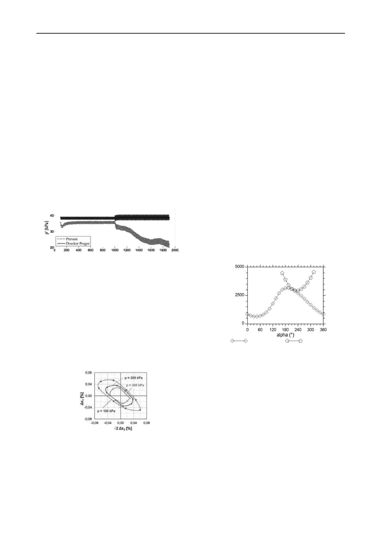
tripod offshore foundation for wind turbines is modelled. As
shown in Fig.5, the difference between both models is limited
during the first part of the loading. Conversely, during the
second part, the soil characterized by Prevost’s model shows a
continuous decrease of mean effective stress without reaching a
stationary state. The results computed through this model also
show pore pressure and plastic deformation accumulation which
the Drucker-Prager model is unable to represent.
Figure 5: Comparison between mean effective stresses at 0.5m depth
under the top of the suction caisson for Prevost and Drücker-Prager
models (Cerfontaine et al, #1759).
To assess the soil behaviour, the experimental method of
response-envelopes is discussed in paper #2360 (Hettler et al.).
The stress-path-dependent strain behaviour at low-cycle loading
is studied through drained, stress-controlled triaxial-tests. The
cyclic load in the first direction is repeated until the measured
strains are practically reversible or rather quasi-elastic. It is
found that quasi-elastic behaviour can already occur at low
numbers of cycles. The strain response of the last cycle is
evaluated and plotted. After that, the test is continued with the
same stress increment, but in a different direction in the stress-
space until quasi-elastic behaviour occurs again. In the
response-envelopes (Fig.6), it is found that the size of the
ellipses decreases with increasing mean pressure p and the
ellipses rotates depending on the initial stress state (stress-
induced anisotropy).
Figure 6: Comparison of response-envelopes due to Δ
= 50 kN/m² for
3 different mean pressures p and constant initial stress-ratio η = 0,75
(Hettler et al, #2360).
In paper #2293, Nakai et al. investigates the seismic stability
of a steel fabricated column constructed on liquefiable grounds
with various stratigraphies. A dynamic/static soil-water coupled
finite deformation analysis is performed in the framework of the
Finite Element Method. From the results, it is found that the
plastic deformation is predominant in the liquefied sand layer,
which led to a decrease in acceleration at the ground surface.
However, if the embedment depth was shallow with high
gravity center, the structure would still incline easily due to the
loss of bearing capacity by liquefaction in the subsurface layer
and gradually tilt under its own weight.
When there is a clay layer seated on the liquefiable layer, the
accelerations are amplified in the clay layer leading to an
increase of input acceleration for the liquefiable layer, and there
is thus a risk that the oscillations of the structure would be
increased. In particular, when the thickness of the liquefiable
layer is small, the attenuation of the acceleration in the
liquefiable layer is also small, so the stability of the structure
above is significantly reduced.
5 EARTH WORKS STABILITY
5.1
Retaining walls and excavations
A simplified method is proposed by Serratrice (paper #1697) to
find the equilibrium of a wall submitted to seismically induced
pseudo-static loads. The failure mechanism involves two
wedges. The example of a purely frictional soil is depicted in
Fig.7. The angle between the horizontal axis and the direction of
the pseudo-static force is denoted
. The computation is
performed in three iterations on the friction angle to reach
equilibrium (for
= 29.5). The value of
is approximately
= 210. As shown in Fig.7, the moduli S of the forces do not
correspond to the maximum of the active force and the
minimum of the passive force. The results compare well with
that from Shukla et al. (2009).
The method is also extended with the introduction of water
pressures. The equilibrium is then considered in terms of
effective stresses. It allows the comparison between both cases
(effective stresses and total stresses).
active
modulus S (kN)
passive
Figure 7: Active and passive earth pressures with respect to angle
for
a soil resistance leading to the equilibrium of a wall (Serratrice, #1697).
In paper #2628 by Khomyakov, the excavation of deep
ditches is investigated in order to determine the optimum
scheme of excavation and slope fixing strategy. Laboratory
experiments in a tray show the efficiency of soil anchors to
ensure the stability of the slope of a ditch. Numerical
simulations are also performed for an optimal design of the
anchoring system (number of lines, length, etc). The optimal
parameters depend on the soil type.
5.2
Earth dams, embankments
Four papers deal with the seismic response and stability of earth
dams and embankments.
The safety conditions of embankments in static and seismic
conditions are investigated by Gottardi et al. (1766) as a
function of the soil parameters variability, seismic hazard
features and considering various relevant river water levels.
Geotechnical and geological field investigations are conducted
in order to identify several representative sections of the
riverbank. Detailed field and laboratory soil characterizations
are then performed (CPTU, oedometric, resonant column).
From these parameters, static and seismic stability analyses are
proposed. Stability maps of the investigated area based on the
data spatial variability are derived (probabilistic approach).


