1172
Proceedings of the 18
th
International Conference on Soil Mechanics and Geotechnical Engineering, Paris 2013
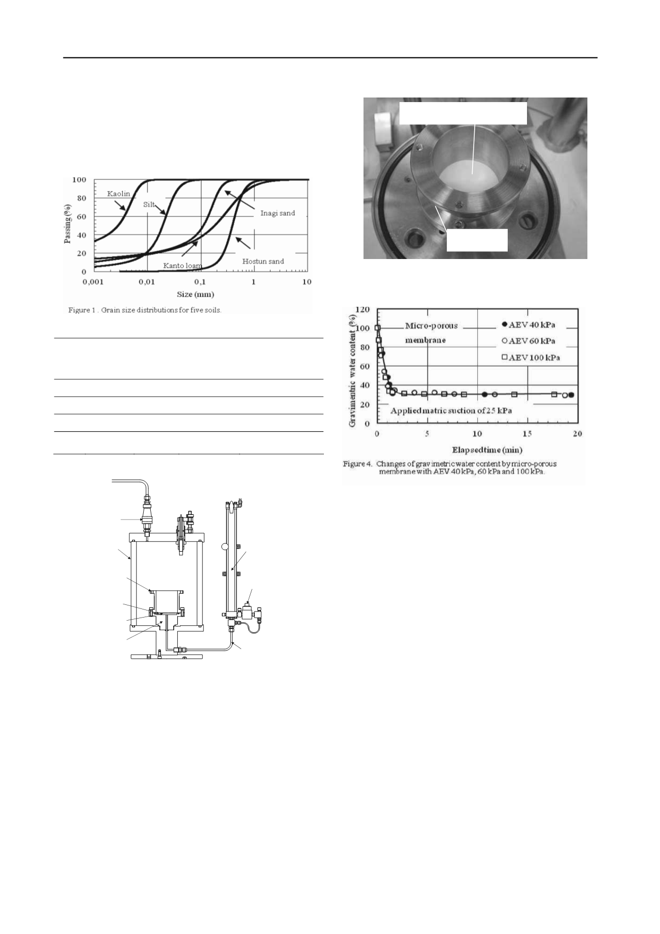
manufactured by Pall. Corporation (
. Two
different types of membranes (i.e., polyether sulfone and acrylic
copolymer) were used in this testing program as summarized in
Table 1. The air entry values of the membranes range from 40
kPa to 250 kPa depending on the pore size and manufacturing
process.
Table 1. Micro-porous membranes used in the test program.
No
Thickness
(μm)
Air entry
value
(kPa)
Pore
diameter(μm)
Material
1
140
250
0.45
Polythersulfone
2
140
100
0.8
Polyther sulfone
3
94
60
0.8
Acrylic copolymer
4
94
40
1.2
Acrylic copolymer
Figure 2. Illustration of the modified SWCC apparatus.
2.2 Modified SWCC apparatus with micro-porous
membrane
The study utilized the new soil-water characteristic curve
apparatus (i.e., SWCC apparatus) as shown in Fig. 2. The
modified SWCC apparatus consisted mainly of a pedestal, a
steel mold, a triaxial chamber and a double glass burette
connected to a differential pressure transducer. Fig. 3 shows the
saturated micro-porous membrane in the steel mold. The steel
mold has an inside diameter of 60 mm and a height of 65 mm.
The pedestal was attached to the triaxial base plate. The water
compartment was connected to the base of the triaxial cell and
the double glass burette. Soil water was allowed to flow into
the double glass burette. A differential pressure transducer was
attached to the lower portion of the double glass burette
Micro-porous membrane
.
A pressure plate apparatus with a ceramic disk was used to
compare the results with those obtained from using the new
micro-porous membrane apparatus. The high air entry ceramic
disk was installed into the pedestal in place of the micro-porous
membrane. The ceramic disk had a thickness of 7 mm and an
air entry value of 200kPa or 500 kPa.
2.3 Soil-water characteristic curve, SWCC, tests
Soil-water characteristic curve tests were performed in the low
matric suction range with a maximum matric suction of 20 kPa.
Drying and wetting paths were established by progressively
increasing and decreasing matric suction. The soils were
prepared in a slurry condition at a high gravimetric water
content. Soil water moved in response to the externally applied
air pressure and accumulated in the burette with elapsed time.
The gravimetric water content of the soil specimen was
calculated from the changes in the amount of water in the soil.
When the water level in the burette attained a steady state
condition, it was assumed that equilibrium conditions have been
attained with regard to the applied matric suction. As a result,
the air pressure supplied to the triaxial chamber was equal to the
matric suction in the soil specimen. The matric suction was
progressively increased up to about 20 kPa. After the
application of the applied maximum matric suction, the air
pressure in the chamber was decreased following the path of
decreasing matric suction.
Steel mold
Figure 3. Assembly steel mold with developed pedestal.
Acrylic cell
Steel mold
Micro-porous
membrane
Difference pressur
sensor
Double glass
burette
Air supply air
pressure
Pedestal
Porous stone
Water tube leading
e


