1176
Proceedings of the 18
th
International Conference on Soil Mechanics and Geotechnical Engineering, Paris 2013
the pressure plate apparatus. These differences can lead to
significantly different SWRC results as compared to the ones
obtained with others methodologies
.
Seeking the development of an accurate low cost alternative
for direct evaluation of the SWRC and also in order to
overcome the considerable large time lag necessary for SWRC
evaluation by conventional methodologies, an alternative
methodology is proposed in this manuscript for SWRC
evaluation that uses a commercially available small centrifuge,
without the need of in-flight instrumentation. Since there is no
external invasive instrumentation (such as TDR probes,
tensiometers, etc), the methodology allows evaluating the
SWRC of undisturbed soils samples
.
The methodology proposed was applied in determining the
SWRC of a young residual soil using both, undisturbed and
remolded soil specimens. The SWRC testing results show good
agreement to the similar data obtained using filter-paper
method, porous plate funnel and suction plate extractor.
2 TESTING SETUP AND THEORETICAL
BACKGROUND
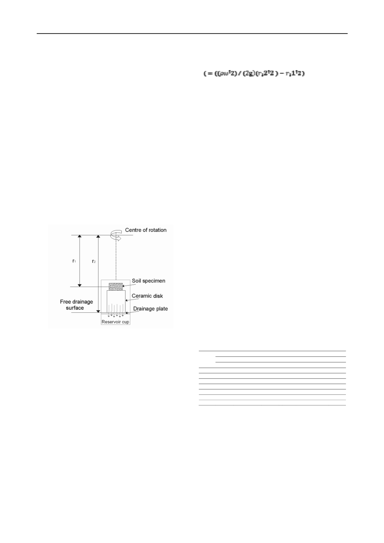
A schematic drawing of the testing setup developed is depicted
in Figure 1.
Figure 1. A schematic drawing of the centrifuge basic principle
Basically, the setup is composed by a water reservoir
located underneath a drainage plate and a high flow ceramic
disk fitted above this drainage plate. A 20 mm thick soil
specimen, fitted into a stiff stainless steel cylinder, used to avoid
any horizontal strains during testing, is placed above the
ceramic disk. A saturated filter paper is placed between the soil
specimen and the ceramic disk in order to prevent soil particles
from migrating into the ceramic disk during testing. The entire
setup is assembled into small centrifuge equipment specially
modified for receiving four testing setups simultaneously. The
drainage plate induces a free drainage surface at the bottom
boundary of the ceramic disk in order that all water flow
coming from the soil specimen is fully transmitted to the
collection reservoir located underneath. The high flow ceramic
disk has two important roles. First, it works by positioning the
soil specimen at a given distance from the centrifuge axis of
rotation. Second, it acts as a dripping surface at the specimen´s
bottom boundary in order that the water outflow rate will be
dictated by the saturated hydraulic conductivity of the soil
specimen and by the induced gravity applied. High flow
ceramic disks with 12 mm and 63 mm thick were specially
manufactured using specific mixes of kaolin and water. The
porosity of the ceramic disks after be placed in the oven was
approximately 48% and the saturated hydraulic conductivity of
the order of 10
-4
cm/s. The suction at any point within the soil
specimen is then evaluated using Eq. [1] proposed by Corey
(1977). Mathematically, the suction is given by:
(1)
where
is the suction magnitude within the soil specimen at a
given distance r
1
measured from the center of rotation, r
2
is the
distance from the center of rotation to the dripping surface,
is
the fluid density,
is the angular velocity (in radians per
second) and
g
is the earth´s gravity. For suction estimate
purpose, r
1
is set as the distance from the center of rotation to
the middle height of the soil specimen. This distance can be
changed by changing the ceramic disk thickness located
underneath. The Eq. (1) defines a nonlinear relationship
between the soil suction and the centripetal radius. The distance
from the center of rotation to the dripping surface (
r
2
) is kept
constant during testing. Analyzing Eq. (1) it can be noted that
any change in the radial distance
r
1
will give a different
magnitude of suction within the soil specimen. Therefore, using
ceramic disks with different thicknesses will induce different
suction magnitudes applied to the soil specimen´s bottom
boundary at a certain speed of rotation. The magnitude of the
suction applied can also be increased simply by increasing the
centrifuge angular velocity. Several centrifuge tests were carried
out to verify the validity of Eq. [1] on estimating accurately the
suction magnitude within the soil specimen. Basically, the
procedure adopted consisted in comparing the soil moisture
value reached after spinning and the correspondent suction
magnitude estimated using Eq. [1] to the experimental data of
the SWRC determined using conventional methods. In all tests
carried out, Eq. [1] presented good agreement to the
experimental data obtained by conventional methods. Table 1
summarizes the soil suction magnitudes at the center that a 20
mm thick soil specimen will be submitted under several angular
speeds using the two different high flow ceramic disks. The
testing procedure consists in assembling two soil specimens
over two 63 mm thick ceramic disks and other two specimens
over two 12 mm thick ceramic disks. Once the centrifuge
equipment was modified to fit four soil specimens
simultaneously, the identical ceramic disks thicknesses setups
are displaced on swinging buckets located on opposite sides of
the centrifuge center of rotation. This procedure allows
submitting two sets of two soil specimens to different values of
soil suction simultaneously at a given angular velocity.
Table 1. Suction magnitudes attained to different ceramic disks and
angular velocity,
.
ω (rpm)
Suction
( kPa) (Corey 1977)
ceramic disks 12 mm
ceramic disks 63 mm
central region
central region
300
2.8
9.3
500
7.9
25.9
1000
31.3
103.7
1500
70.4
233.3
2000
125.2
414.7
2500
195.7
647.9
3000
281,8
932,71
3 EXPERIMENTAL COMPONENT
The testing program was carried at the Civil Engineering
Laboratory (LECIV) of the State University of Norte
Fluminense Darcy Ribeiro (UENF). The centrifuge equipment
used was a Cientec CT 6000 small-scale centrifuge specially
adapted with four swinging buckets. The testing program
consisted in evaluating the SWRC of a young residual soil from
gneiss using both, undisturbed and remolded soil specimens.
The soil is classified as clayey silt sand. The undisturbed soil
specimens sets, identified herein as undisturbed young horizon
(UY), were sampled with a 50mm diameter 20 mm height rings.
The remolded samples sets, identified as remolded young
horizon (RY), were obtained by handling undisturbed soil
samples and re-compacting them statically in order to achieve
same dry unit weight in all specimens of each set. This


