706
Proceedings of the 18
th
International Conference on Soil Mechanics and Geotechnical Engineering, Paris 2013
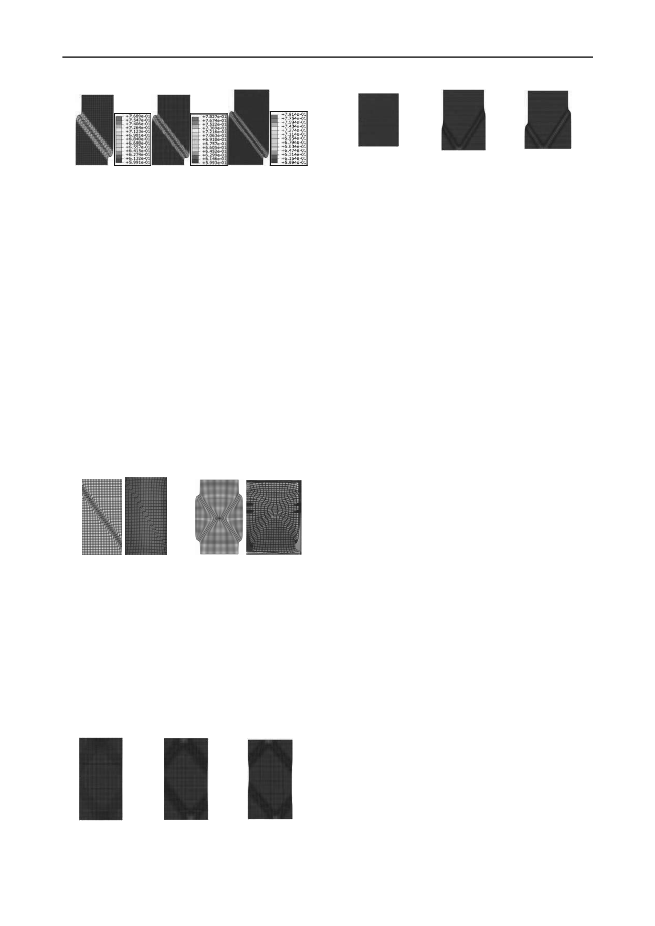
(a) coarse mesh
(b) medium mesh
(c) fine mesh
Figure 5. Deformed finite element mesh along with contour plot of void
ratio for (a) coarse mesh, (b) medium mesh, and (c) fine mesh
It has been reported from experimental observations of
biaxial compression tests (Alshibli and Sture 2000) that the
behavior of granular materials is dependent on the boundary
conditions of specimen. The following simulations illustrate the
boundary condition effect on the shear band formation. The
finite element calculations are performed for two separate cases:
(1) smooth and (2) very rough surfaces at the top and bottom of
specimen. The obtained finite element results are compared
with those of experiments (Alshibli and Sture 2000). Figure 6
displays that multiple shear bands develop in the specimen
when the bottom boundary is very rough (Figures 6(c) and
6(d)). The finite element results demonstrate that shear band
location and mode are highly influenced by the prescribed
boundary conditions, prescribed along the top and bottom
surfaces of specimen (Figures 6(a) and 6(c)), which are
consistent with experimental observations (Figures 6(b) and
6(d)) (Alshibli and Sture 2000). According to finite element
results, two principal mechanisms of shear banding may occur
in granular materials under plane strain compression: in the first
mechanism, a single shear band is formed inside the specimen
(Figures 6(a) and 6(b)), while in the second, more than one
shear band can occur if the movement of bottom boundary is
restrained under plane strain condition (Figures 6(c) and 6(d)).
(a)
(b)
(c)
(d)
Figure 6. Comparison between shear banding patterns obtained from
numerical simulations and experiments (Alshibli and Sture 2000): (a)
and (b) free rotational boundary, (c) and (d) restrained rotational
boundary
The behavior of granular material is also affected by the
geometry of specimen. If the length to width ratio of specimen
would be larger than 2.0, then the failure will not, to some
extent, be affected by the boundary conditions and a single
shear band is formed (Figure 5). For the ratio equal to 2.0, a
complicated pattern of shear banding is developed within the
specimen, as shown in Figures 7(a)-7(c). For smaller values of
length to width ratio, a reflection of shear band is observed
when it hits the bottom rigid boundary (Figures 7(d)-7(f)).
Axial strain = 13%
Axial strain = 5%
Axial strain = 2%
(c)
(b)
(a)
Axial strain = 13%
Axial strain = 5%
Axial strain = 0%
(f)
(e)
(d)
Figure 7. Shear band formation process in biaxial specimen with
different geometries: (a), (b), (c) length to width ratio = 2, and (d), (e),
(f) length to width ratio = 1.33
5 CONCLUSION
An extended elasto-plastic Lade’s model along with
embedded Cosserat rotations and couple stresses, can simulate
properly the localization phenomenon in the granular materials
under different loading conditions. Polar quantities are
noticeable in the shear band. Cosserat rotations, increasing void
ratios, high gradient of micro-curvatures and couple stresses can
be used to identify the shear band. The couple stress values is
found to be very small in magnitude compared with the stresses;
however, they have significant effects on the material behavior,
partucularly in the softening regime. Location and evolution of
shear bands are mainly affected by the micro-polar kinematical
boundary conditions and rotation resistance of soil grains
prescribed along the boundries. The length scale and size of
specimens have substantial influence on observed pattern of
shear banding in granular materials.
6 REFERENCES
Hall S.A., Bornert M., Desrues J., Pannier Y., Lenoir N., Viggiani G.
and Bésuelle P. 2010. Discrete and continuum analysis of localised
deformation in sand using X-ray μCT and volumetric digital image
correlation.
Géotechnique
60(5), 315-322.
de Borst R. 1991. Simulation of strain localization: a reappraisal of the
Cosserat continuum.
Engineering Computations
8, 317–332.
Mühlhaus H.B. 1986. Shear band analysis in granular materials by
Cosserat theory.
Ingenieur Archiv
56, 389-399.
Vardoulakis I. and Sulem J. 1995.
Bifurcation Analysis in
Geomechanics
. Blackie Academic & Professional, Glasgow, UK.
Lade P.V. and Kim M.K. 1988. Single hardening plasticity model for
frictional materials.
Computers and Geotechnics
6, 13-29.
Kim M.K. and Lade P.V. 1988. Single hardening constitutive model for
frictional materials.
Computers and Geotechnics
5, 307-324.
Ebrahimian B., Noorzad A. and Alsaleh M.I. 2012. Modeling shear
localization along granular soil–structure interfaces using elasto-
plastic Cosserat continuum.
International Journal of Solids and
Structures
49, 257–278.
Oda M. and Iwashita K. 2000. Study on couple stresses and shear band
development in granular media based on numerical simulation
analyses.
International Journal of Engineering Science
38, 1713-
1740.
Vardoulakis I. 1980. Shear band inclination and shear modulus in
biaxial tests.
International Journal of Numerical and Analytical
Methods in Geomechanics
4, 103-119.
Desrues J., Chambon R., Mokni M. and Mazerolle F. 1996. Void ratio
evolution inside shear bands in triaxial sand specimens studied by
computed tomography.
Géotechnique
46, 529-546.
Alshibli K.A. and Sture S. 2000. Shear band formation in plane strain
experiments of sand.
ASCE Journal of geotechnical and
geoenvironmental engineering
126(6), 495-503.


