708
Proceedings of the 18
th
International Conference on Soil Mechanics and Geotechnical Engineering, Paris 2013
this formulation, two contact surface pairs with specific
interaction model were defined. At the pile-soil and wall-soil
interface, a basic Coulomb frictional interaction model was
assigned to define the interaction between the soil and wall
surfaces. This model defines the maximum allowable frictional
(shear) stress that can be transferred across the interface as the
contact pressure between the contacting bodies multiplied by a
friction coefficient. For the purpose of this study, a friction
coefficient (
) of 0.50 was assumed.
i of elasticity, density, and passion’s ratio shown in
Ta
eet pile section moduli defined by PU steel
sheet pile walls.
oment distribution along the pile was calculated
using Eq (1).
1.2
Input parameters and model variables
Input parameters considered in the analyses included soil
mechanical properties (density, shear strength parameters, and
elastic modulus) as well as pile and wall material properties.
The soil considered for this study was medium dense sand
modeled as an isotropic elasto-plastic material with a Mohr
coulomb failure criterion as provided in Table 1. The pile and
wall were modeled as isotropic linearly-elastic materials defined
by modul
ble 2.
Model variables considered in assessing the effect of wall
stiffness (E
wall
I
wall
), pile stiffness, excavation depth- to pile
length ratio (H/L), and distance of pile from the wall (X) are
summarized in Table 3. It should be noted that pile diameter (d)
was considered as a representation of pile stiffness.
Furthermore, wall stiffnesses shown in Table 3 correspond to
different steel sh
1.3
Modeling approach
The finite element modeling was executed in three stages. The
first stage involved the generation of the initial effective
geostatic stress within the model. This was performed by
applying a gravity load of 10 m/sec
2
on the entire model. At the
end of this stage, the analysis output was checked to ensure
triangular distribution of vertical stress (i.e., increasing with
depth) accompanied by small vertical deformations. In the
second stage, the pile and wall was introduced and contacts
along pile-soil and wall-soil interface were activated. Finally,
staged excavation was modeled by the removal of model
elements in phases each of 1 m thick up to a total excavation
depth of 5 m. Output fields monitored at the end of each
excavation stage included lateral deflection and axial strain
along pile shaft. Based on the axial strain along the pile shaft,
the bending m
I E
)( )(
pile
pile
r
z
zM
b
(1)
the moment of inertia of the pile; and
r
is the radius of the pile
2 RESULTS AND DICUSSION
0 mm will be illustrated in figures
presenetd in this section.
al deflection and bending moment distribution along
l deflection at H/L = 0.5 depends on the
pil
where
M(z)
is the bending moment at any depth z from pile
head;
b
(z)
= bending strain at depth z from pile head = (
1
-
2
)/2
;
1
2
=
axial strains at outermost elements located on both
sides of neutral axis; E
pile
is the elastic modulus of pile; I
pile
is
This section summarizes main findings obatined from the finite
element analyses. For clarity and paper page limitaiton, only
results related to d = 60
2.1
Later
pile
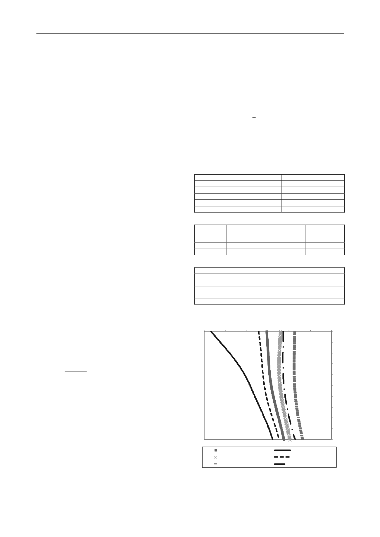
Figures 2 and 3 show distributions of pile lateral deformation
and bending moment for different excavation depths. As shown
in Figure 2, pile lateral deflection increased with increase in
excavation depth and decreased with increase in pile distance
from the wall (X). Furthermore, change in the profile of lateral
deflection was observed for pile of X = 2 m when H/L increased
from 0.4 to 0.5 signifying that the pile underwent excessive
lateral deformation due to wall deformation. The magnitude
and shape of the latera
e stiffness (i.e., d).
Bending moment distributions along pile length for different
X and H/L are illustrated in Figure 3. From Figure 3, it is
observed that, for H/L < 0.4, bending moment had a one sided
parabolic distribution; however, for H/L = 0.5, bending moment
distribution showed degree of moment direction reversal. This
is attributed to significant change in lateral deformation profile
(Figure 2). The degree and magnitide of moment direction
reversal decreased with increase in X as shown in Figure 3.
Furthermore, it was observed that the degree of moment
versal increases with increase in pile stiffness.
Table 1. Inpu
meter
V e
re
t parameters of soil
Para
alu
Cohesion (c, kPa)
5
Angle of friction (
, degree)
35
Poisson’s ratio
0.35
Density (
, kg/m
3
)
1800
Elastic modulus (E, kPa)
50000
Table 2. Input para
pile and w
Component
(
, kg/m
3
)
(E,
a)
Poisson's ratio
meters of
all
Elastic
Density
modulus
MP
Pile
2500
25
0.15
W
7800
200
0.30
all
Table 3. Modelin
s
g variable
Variable
Value
Pile diameter (d)
300,
mm
600, 1000
Pile distance from the wall (X)
2, 4, 8 m
Wall stiffness (E I )
1.
,
wall wall
45x10
5
, 6.10x10
4
2.32x10
4
kN.m
2
Excavation depth-to-pile length rati H/L)
0.1, 0.2, 0.3, 0.4, 0.5
o (
0
1
2
3
4
5
6
7
8
9
10
-6
-5
-4
-3
-2
-1
0
Pile Depth (m)
Pile lateral deflection (mm)
X = 2 m, H/L = 0.4
X = 2 m, H/L= 0.5
X = 4 m, H/L= 0.4
X= 4 m, H/L= 0.5
X = 8 m, H/L = 0.4
X= 8 m, H/L = 0.5
Figure 2 Lateral defelction distribution along pile (d = 600 mm, E
wall
I
wall
= 6.10 x10
4
kN.m
2
)


