701
Technical Committee 103 /
Comité technique 103
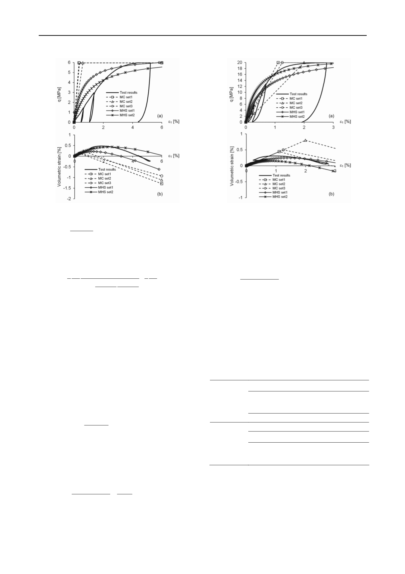
Figure 4. (a) Deviatoric stress and, (b), volumetric strain as a function of
axial strain under a radial stress of 2 MPa (parameters: Table 1)
*
3
2sin
1 sin
*
m
m
q q
.
(10)
Substituting Eq. (10) into Eq. (7) and considering that
q
f
=
R
f
q
a
leads to Benz et al.’s (2008) formulation of the yield function:
*
*
50
3
1
3
( ,
)
1 sin sin
4
2
1
sin 1 sin
ps
ps
s
s
f
m
ur
f
f
m
q
q
f
E
E
R
11)
s mentioned by Benz et al. (2008), Eq. (11) is not limited to
(12)
here
I
1
*
,
I
2
*
and
I
3
*
are the transformed stress invariants.
n-associated and corresponds to
the
,
(
A
the Mohr-Coulomb failure criterion. In order to consider the
effect of intermediate stress and simplify the numerical
implementation they adopted the smooth Matsuoka-Nakai yield
surface:
* *
2
*
2
1 2
3
(1 sin )
(9 sin ) 0
m
m
I I
I
,
w
Based on this equation, the mobilized friction angle can be
expressed in terms of the stress invariants and inserted into Eq.
(11), which leads to the yield function of the MHS model for
the Matsuoka-Nakai criterion.
The adopted flow rule is no
cone-shaped plastic potential Drucker-Prager function:
*
*
6sin
( )
3 sin
m
m
q p
,
(13)
here
m
denotes the mobilized dilatancy angle. The original
w
HS model assumed Rowe’s (1962) dilatancy law, which,
however, greatly overestimates the contractant behavior at low
mobilized friction angles (Benz 2008). The MHS model adopts
the relation of Soreide (1990):
sin sin
sin
sin
1 sin sin sin
m
cs
m
m
m cs
f
,
(14)
here
cs
is the so-called critical mobilized friction angle. This
w
parameter marks the boundary between contractant and dilatant
behavior.
Figure 5. (a) Deviatoric stress and, (b), volumetric strain as a function of
axial strain under a radial stress of 9 MPa (parameters: Table 1)
If the mobilized friction angle is lower than the critical
mobilized friction angle, the mobilized dilatancy angle is
negative, which means that the behavior is contractant.
Otherwise the behavior is dilatant. The critical mobilized
friction angle depends on the final values of the friction and
dilatancy angles:
sin sin
sin
1 sin sin
f
f
cs
f
f
.
(15)
As mentioned above, the MHS model does not include the cap
hardening part of Benz’s (2008) HS model. Under the
conditions prevailing in triaxial tests as well as in the ground
around deep tunnels, the stress path corresponds to mainly
deviatoric shearing. The behavior can be solely simulated by the
deviatoric hardening part, i.e. without considering cap
hardening. In the absence of the latter, the parameters can be
determined using conventional triaxial tests (no oedometric or
isotropic compression tests needed) and the numerical
implementation is simplified.
Table 1. Parameter values
MC model
Parameters
Set 1
Set 2
Set 3
E
[MPa]
1800
1000
1600
[°]
6.4
6.4
5
Other parameters:
=
0.3,
c
= 0.569 MPa,
= 30°
MHS model
Parameter
Set 1
Set 2
m
0.91
1.88
Other parameters:
E
ur,ref
= 1800 MPa,
E
50,ref
=
1152
MPa,
p
ref
= 5 MPa,
=
0.3,
c
f
=
0.569 MPa,
f
=
30°,
= 6.4°,
R
f
=
0.9
The MHS model has a total of nine parameters, four of them
(
E
ur,ref
,
E
50,ref
,
p
ref
,
m
) are used to determine the moduli
E
ur
and
E
50
. Another 4 parameters are same as in the Mohr-Coulomb
model (
,
c
f
,
f
and
f
). The last parameter
R
f
, which defines the
ratio between
q
f
and
q
a
, is usually taken equal to 0.9. As with
the MC model, all the parameters have a clear physical meaning
and can be determined using conventional triaxial tests.


