713
Technical Committee 103 /
Comité technique 103
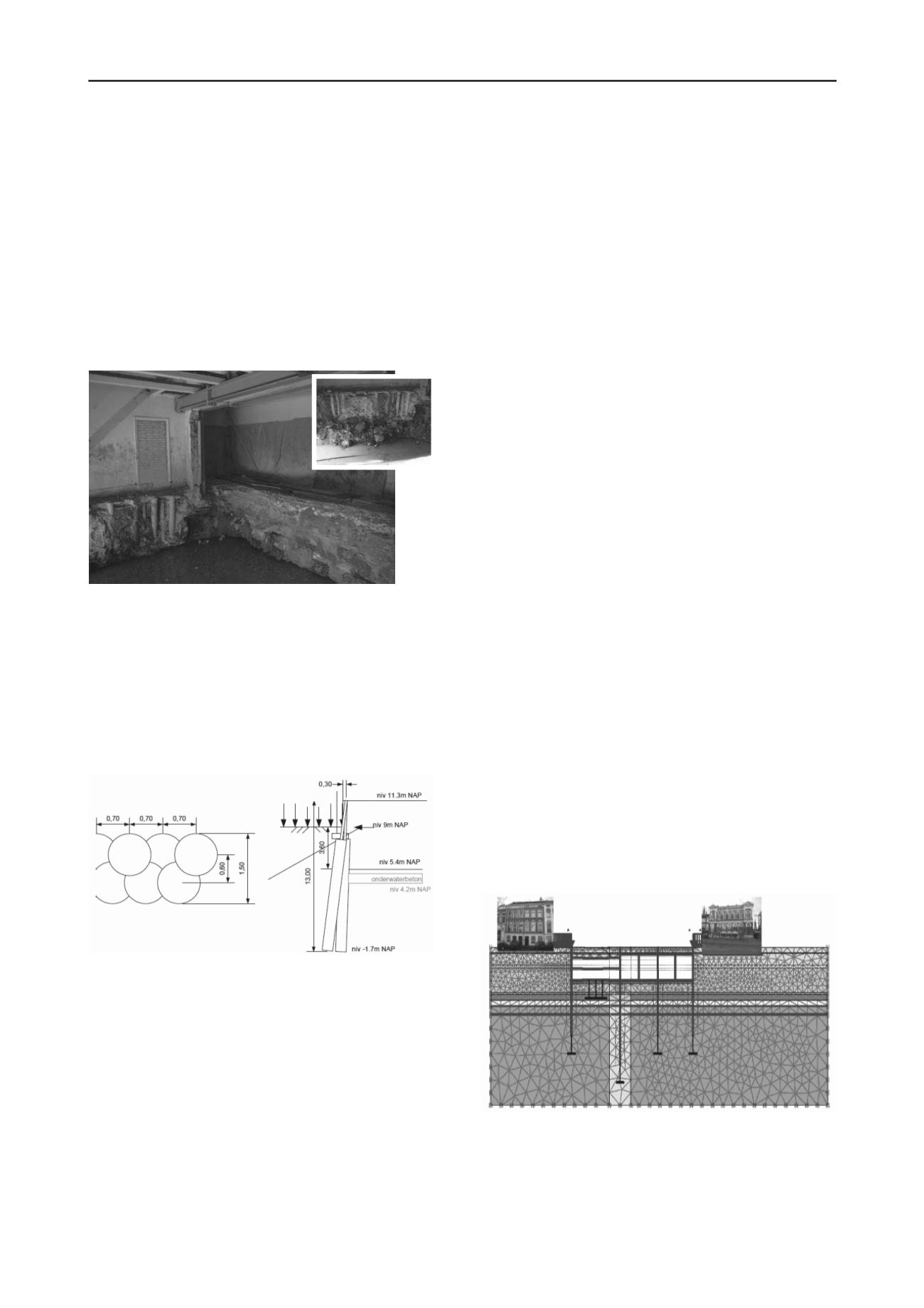
has a grout diameter of about 0.9 m with an overcut of about 0.2
m up to 0.3 m. The column dimensions are verified by
continuous monitoring of jet pressure and injected grout
volumes.
The jet grout walls are installed from foundation level (NAP
+9.0 m) to tip level at NAP -2.5 m (Figure 2). To reduce the risk
of failure of the foundations the installation sequence of the
grout columns is adjusted. At critical locations larger intervals
between fresh casted columns is applied. The columns are
reinforced to obtain the required strength and stiffness.
FEM analysis with PLAXIS 2D and 3D is used to assess the
wall thickness and excavation sequence with underwater
concrete floor and anchor piles. And to predict and postdict the
deformations of the existing foundations.
Figure 1. Indoor wet excavation.
To model the jet grout wall with Mohr Coulomb, the
strength and stiffness were calculated by means of the ultimate
compression strength
f
c
= UCS using the empiric relations of
Van der Stoel (2001):
;
o
soil
à
5 0
'
'
c
f
à c
0.3 2.0 '
;
;
5,0
67,0
2,0
;50
800
c
sand
f
E
;50
500
c
clay
f
E
Figure 2. Jet grout wall.
4 SELECTION OF METHOD
4.1
General
Modelling method selection is part of the design process. The
engineer should have an overview of environmental features
such as foundation types of contiguities, dimensions and soil
profile and properties. To make the selection several questions
need to be answered. What information should the model
produce? What loads are applied on the diaphragm wall
(vertical, lateral, both)? Should deformations be quantified of
buildings supported by shallow foundations or deep
foundations? Are the retaining walls connected to concrete slabs
and temporary struts? Are properties of such structural elements
critical to the performance of the construction in relation to
deformations.
Where modelling ground surface response at the active side
should be emphasised for (temporary and multiple) supported
walls, Method 1 is recommended.
In cases of modelling vertically loaded walls, interaction
with neighbouring pile foundations or other walls (group
effects) Method 2 is recommended.
4.2
Railway tunnel Delft – Method 1
Primary focus for this project was assessment of the
deformations of buildings and monuments. The allowable
deformations of the contiguities are very small and were
according to an amplified Boscardin and Cording (1989)
approach. They are combinations of angular distortion and
horizontal strain. Most buildings in Delft are supported by
shallow foundations with foundation levels at about 0.8 m
below ground surface.
In co-operation with structural engineers the tunnel outline
was designed. Detailed geotechnical analyses comprised FEM
in order to assess the interaction of the tunnel construction with
the environment for each distinguished construction stage. A
flexible design model was required to allow for rapid
modifications in the model where the building deformation
criteria were not met.
The emphasis was put on surface settlement assessment and
verification of preliminary structural design. Method 1 was the
appropriate model.
Along the tunnel alignment the buildings were classified
based on the allowable additional deformation, from slight to
negligible. The condition of each building was accurately
recorded. This way imperative behavioural design could be fit
to each individual building case.
Finite element models (Plaxis 2D and Plaxis 3D) were used
to assess the deformations of the tunnel system. The model does
not take account of interaction between soil and foundation
slabs. It assesses green field deformations outside the tunnel
trench. The deformations at foundation level can be extracted
from the model.
Using a cross section over Phoenixstraat 30 and Spoorsingel
25 (Figure 3) the deformation analyses is explained. Figure 4
shows a location map with the location of the example cross
section. The building Phoenixstraat 30 has an old part which is
in poor conditions (class IV) and a new part which is in fair
conditions (class II). There is a basement below the building at
about 2.0 m below ground surface. The building Spoorsingel 25
(class III) opposite of Spoorsingel 30 does not have a basement.
This building has a foundation level at 0.8 m below ground
surface.
Figure 3. Cross section FEM Method 1
Calculations proved that additional measures are required to
limit the horizontal deformation of the diaphragm wall during
the first excavation stages. Measures selected for this cross
section are the introduction of additional struts at surface level
and the use of 3.8 m wide diaphragm wall panels (standard
width 7.5 m).


