720
Proceedings of the 18
th
International Conference on Soil Mechanics and Geotechnical Engineering, Paris 2013
the development of the pore water pressure for the area below
the water level as presented in Pichler et al. (2012).
3.1
Numerical Model
As a current restriction of the dynamic coupled 2-phase
approach two-dimensional plain strain analysis have to be
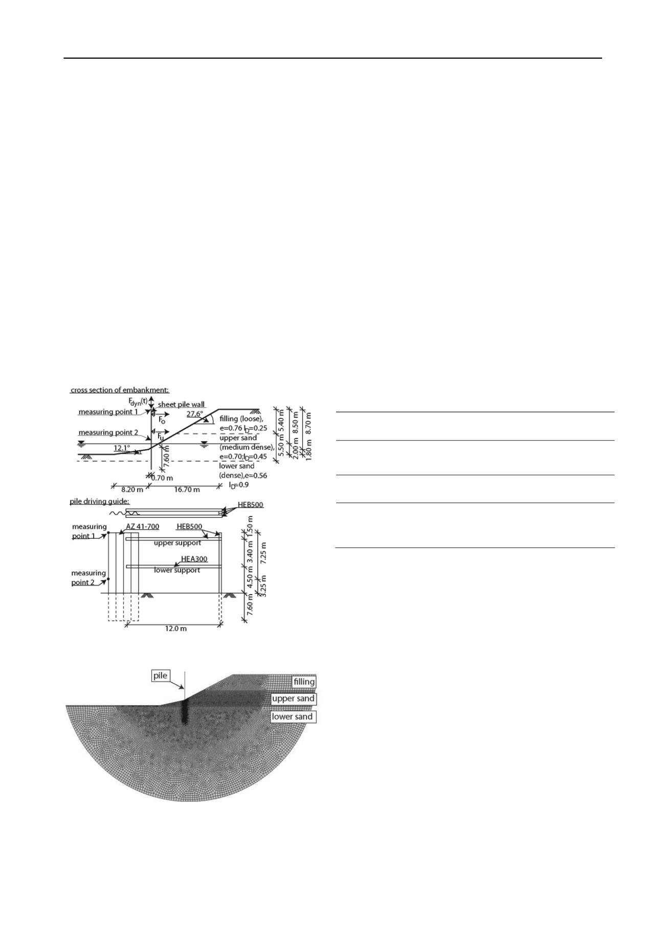
carried out. The geometry and dimensions of the investigated
cross section as well as the height of the water level are depicted
in Figure 1. At the bottom and sideways surface of the soil body
of the finite element model (see Figure 2) the displacement
boundaries are fixed in vertical and horizontal direction and a
hydrostatic pore water pressure is assumed. The sheet pile is
modeled as a deformable body with a linear elastic material
behavior. A Young’s modulus of
E
= 210,000 MN/m² and a
Poisson’s ratio of
= 0.3 are assumed for the steel. Due to the
elastic material behavior of the sheet pile a realistic wave
propagation within the pile and lateral oscillations of the pile
during the vibratory driving can be modeled. The sheet pile is
modeled wished-in-place at its final penetration depth. The
underlying assumption regarding the penetration process is, that
the surrounding soil is mainly influenced by shaft friction. Toe
resistance plays a minor role. The point of load application is at
the head of the sheet pile.
Figure 2. Finite element model with discretisation.
3.2
Constitutive model of the sand
A hypoplastic constitutive model is used to describe the non-
linear and anelastic behavior and the dynamic compaction
process of the sand being present in the embankment
realistically. The hypoplastic model in the version of Gudehus
(1996) and von Wolffersdorff (1996) in the formulation of von
Wolffersdorff (1996) with the extension of intergranular strains
by Niemunis and Herle (1996) is used. Modeling the sand by
use of hypoplasticity, typical characteristics like dilatancy,
contractancy, different stiffness for loading and unloading as
well as the dependency of the stiffness from the void ratio and
mean pressure can be considered. The sands, present in the
embankment, are relativ inhomogeneous regarding their
composition. Hypoplastic material parameters of the sands in
situ are not available. For simplification the parameters of a so-
called “Karlsruher Sand” are used for each soil layer, even
though they comply with some layers insufficiently. A
distinction between the three soil layers depicted in Figure 1 is
done by specifying the bulk density in terms of an initial void
ratio as depicted in Figure 1. The material parameters of
Karlsruher Sand used in the analysis are given in Table 1.
In simulations considering coupled conditions for areas of the
embankment consisting of water saturated sands the hypoplastic
constitutive model of the solid skeleton is extended. A
continuity equation for the water phase to describe the
development of the pore water pressure is introduced (Pichler et
al. 2012). The flow of the water through the sand is described
by Darcy’s law (Darcy 1856). The permeability was determined
by soil tests and is assumed to
k
f
= 1.0·10
-4
m/s for each soil
layer.
Table 1. Hypoplastic material parameters of Karlsruher Sand.
Parameter
c
(°)
h
s
(MPa)
n
(-)
e
d0
(-)
e
c0
(-)
e
i0
(-)
α
(-)
Karlsruher
Sand
30 5,800 0.28
0.53 0.84 1.00 0.13
Parameter
β
(-)
m
T
(-)
m
R
(-)
R
(-)
β
R
(-)
χ
(-)
Karlsruher
Sand
1.05
2
5 0.0001
0.5 6.0
3.3
Contact formulation
The contact between pile and soil is modeled by use of a surface
to surface contact algorithm (Dassault Systèmes 2009). An
angle of wall friction of
= 2/3
’ with a friction angle of
’ =
30° is assumed. An undrained soil behaviour is assumed at the
contact surface between pile and soil.
3.4
Discretisation
The finite element model depicted in Figure 2 is discretised with
approx. 15,000 four-node plain strain elements with reduced
integration and hourglass control.
3.5
Loading
A geostatic stress state with a hydrostatic pore water pressure
distribution is defined as initial condition. The vibratory driving
of the sheet pile is simulated displacement-controlled to prevent
a penetration of the sheet pile into the finite element mesh of the
soil body as it happens in a force-controlled simulation.
Therefore a harmonically oscillating vertical displacement is
applied to the head of the sheet pile as an external loading for a
period of 10 s. The magnitude of the oscillation is determined
in a short foregoing force-controlled simulation
with a dynamic vibrating force of
F
dyn
= 1500 kN. After the
vibratory driving no external loading except gravity is applied
to the model for a period of 10 s to investigate the behavior of
consolidation in the model.
Figure 1. Top: cross section of the embankment; bottom: engaged pile
driving guide.


