714
Proceedings of the 18
th
International Conference on Soil Mechanics and Geotechnical Engineering, Paris 2013
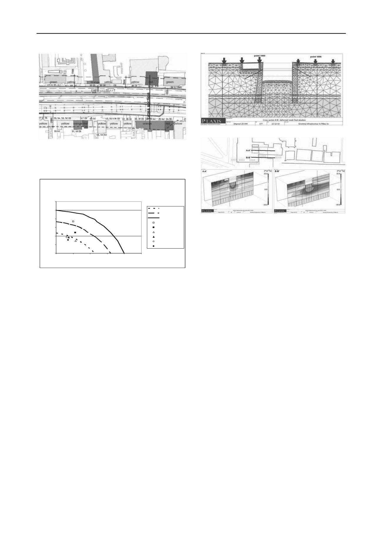
Figure 6. Cross section FEM Method 2.
Figure 4. Cross section location map.
Figure 5 presents an up-scaled graph based on Boscardin and
Cording (1989). It shows that the most critical construction
stage for Phoenixstraat 30 is at the end of the construction of the
eastern tunnel tube (about 50% the total construction period).
RESULTS DEFORMATION PREDICTION
CROSS SECTIONPHOENIXSTRAAT 30 - SPOORSINGEL 25
0
0,2
0,4
0,6
0,8
1
1,2
0
0,5
1
1,5
2
2,5
Angular distortion x10
-3
Horizontalstrainx10
-3
Class IV (red)
Class III (orange)
Class II (yellow)
Ph30-II-50%
Ph30-II-End
SP25-III-50%
SP25-III-End
Ph30-IV-50%
Ph30-IV-End
Class IV
Class II
Class III
Figure 5: Verification of allowable building deformations
Figure 7. 3D-FEM postdiction of vertical displacements.
Note: Figure 7 should be read in combination with Figure 6.
The main reason for selection of Method 2 was to assess
foundation deformations as well as swell deformations of the
bottom of the excavation based on realistic stress distribution.
5 CONCLUSIONS
Comments Figure 5:
Phoenixstraat 30, new part (class II): II-50% (construction stage),
II-End (final stage)
Phoenixstraat 30, old part (class IV) IV-50% (construction stage),
IV-End (final stage)
In this paper two methods are described for finite element
modelling of diaphragm wall supported excavations.
Advantages and disadvantages are given that may contribute to
pre-selection of the model that fits best to the specific project
features.
Spoorsingel 25 (class III) III-50% (construction stage), III-End
(final stage)
The critical construction stage for Spoorsingel 25 is the final
stage. Further, the verification of deformation criteria proves
that the combination of horizontal strain and angular distortion
is met during all intermediate design construction stages.
Method 1 was applied for modelling the railway tunnel in
Delft because of the requirement of flexible design models in
combination with shallow foundations sensitive to
deformations.
For the case in Assen Method 2 was selected. The
requirements for this case better agree with the advantages of
better visualisation of wall and soil behaviour and calculation of
stresses and deformations in soil, wall and foundation.
4.3
Drents Museum Assen – Method 2
One of the critical requirements was the maximum tolerated
settlement and heave of the foundation during the excavation
below the monumental building. The maximum allowable
vertical displacement for the foundations is 5 mm to 10 mm
which corresponds to relative rotations of 1:500 to 1:1,000. The
existing foundations are modeled as separate shallow
foundations (including basement) as shown in Figure 6.
6 ACKNOWLEDGEMENTS
The authors would like to thank their colleague Remy Delpeuch
for the translation of the abstract into decent French.
7 REFERENCES
To evaluate the applied geotechnical calculation models and
the predicted soil and structural behaviour, post diction analyses
with 3D-FEM have been performed (Figure 7) based on the
latest monitoring results during execution. Due to the wet
excavation, the foundation settlement was 4 mm to 9 mm. After
dewatering the excavation, the postdicted foundation rebound
was about 4 mm to 5 mm due to developing tension resistance
in the anchors below the elastic underwater concrete floor
during the instantaneous swell of the underlying soil layers and
the primary swell of the deeper slightly over-consolidated clay.
Boscardin, M.D. and Cording, E.J., 1989. Building Response to
Excavation-induced Settlement.
Journal of Geotechnical
Engineering
(ASCE). 115(1), 1-21
CUR 231, 2010. Handboek diepwanden, Ontwerp en uitvoering.
Stichting CURNET, Gouda
, 2010
EN 9997-1, 2011. Geotechnical design of structures -Part 1: General
rules.
Nederlands Normalisatie Instituut,
December 2011
Van der Stoel, A.E.C., 2001. Grouting for pile foundation
improvements.
Delft University of Technology
, 2001


