669
Technical Committee 103 /
Comité technique 103
Proceedings of the 18
th
International Conference on Soil Mechanics and Geotechnical Engineering, Paris 2013
-1.5
0
1.5
-1.5
0
1.5
0 0.02 0.04 0.06 0.08 0.1
0
100
200
300
400
q
p
=35
0
,
max
=5
0
-1.5
0
1.5
-1.5
0
1.5
-1.5
0
1.5
-1.5
0
1.5
0 0.02 0.04 0.06 0.08 0.1
0
40
80
120
160
q
p
=35
0
,
max
=0
0
0 0.02 0.04 0.06 0.08 0.1
0
200
400
600
800
1000
q
p
=35
0
,
max
=35
0
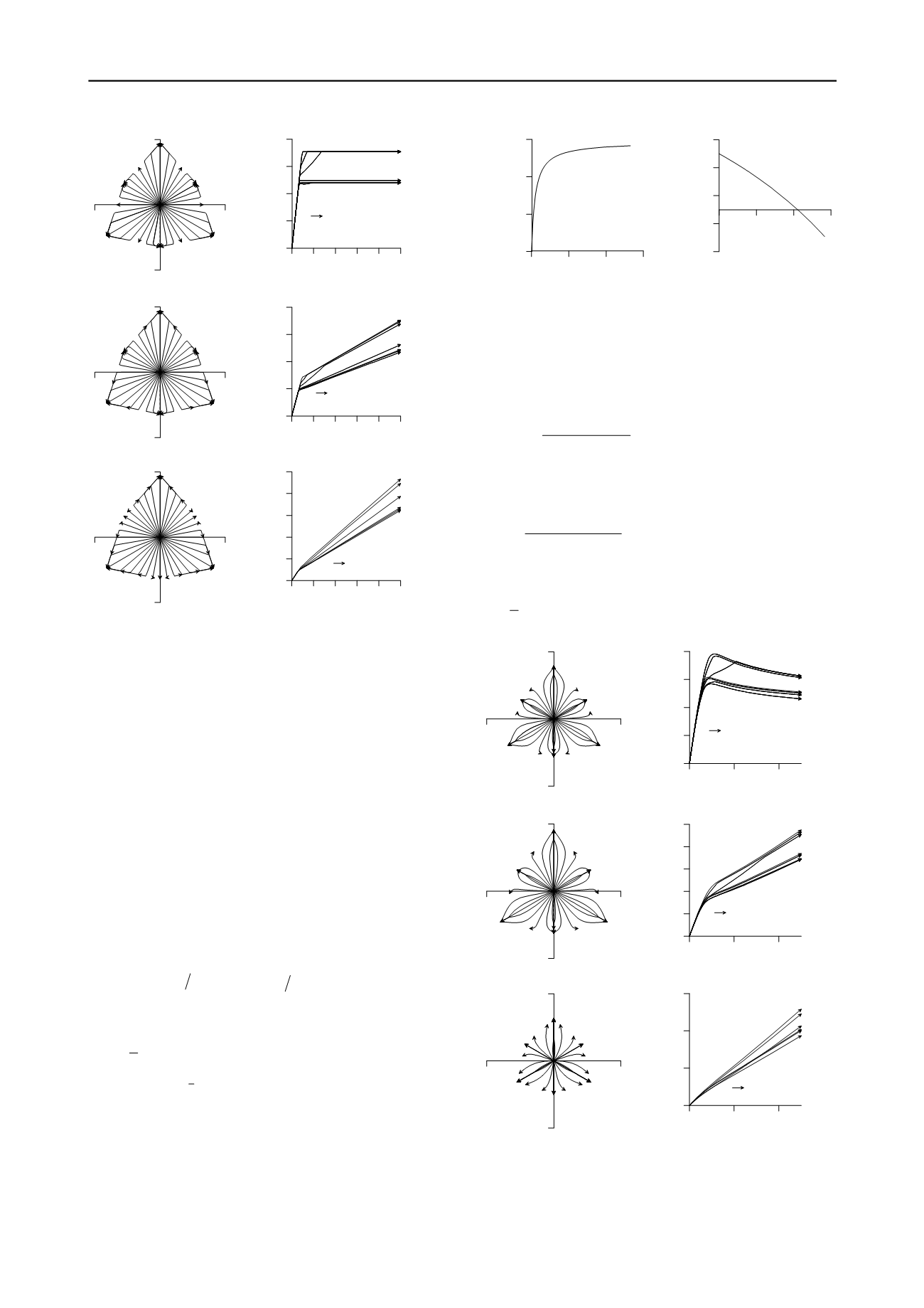
Figure 3
:
Plots of isochoric stress paths (for radial isochoric strain
increments, a) in a deviatoric plane (normalized by mean normal stress)
b)
p-q
plane and c) shear strain deviatoric stress plot, for an elastic
perfectly plastic Mohr-Coulomb model with a Mohr-Coulomb plastic
potential function. For all simulations G=5000kPa and v=0.3 are used.
This, however, will not fully solve the drift problem as
illustrated in simulations using
max
p
y j
=
,
i.e
., associated
plasticity (Figure 2).
4 SIMPLE ELASTIC PLASTIC HARDENING MOHR-
COULOMB MODEL
To formulate a simple hardening model, the peak friction angle,
p
j
, and the maximum dilatancy angle,
max
y
, in Equations (5)
and (6) are replaced by mobilized friction angle,
m
j
, and
mobilized dilatancy angle,
m
y
, respectively (see Figure 4). The
increment of the sine of the mobilized friction angle is related to
the plastic shear strain increment according to
(
)
2
sin
1
p
p
m
m
d
G
d
j
h g
= -
,
(12)
where
p
p
G G p
=
,
sin sin
m
m
p
h
j j
=
,
p
G
is a model
parameter, called plastic shear modulus and
p
d
g
is the plastic
shear strain increment and here is defined as
2
3
2
p
p
d
tr
e
g
=
,
(13)
where
1
3
:
p
p
p
= -
e ε ε δ
is the plastic deviatoric strain rate
tensor.
The plastic volumetric strain increment,
:
p
p
v
d d
ε δ
e
=
, is
calculated as
sin
p
p
v
m
d
d
e
y g
=
,
(14)
where
sin
m
y
is the mobilized dilatancy angle.
0 10 20 30
p
0
0.2
0.4
0.6
sin
m
0 0.2 0.4 0.6
sin
m
-0.2
0
0.2
0.4
0.6
sin
m
Figure 4: a) Hardening rule: mobilization of the sine of friction angle
with plastic shear strains b) Plot of mobilized dilatancy angle with
mobilized friction angle according to Rowe’s stress-dilatancy rule.
The mobilized dilatancy angle is calculated from Rowe’s stress-
dilatancy relationship, which in assuming sign convention of
soil mechanics, is given by
sin sin
sin
1 sin sin
m
c
m
m c
j j
y
j j
-
=-
+
,
(15)
where
c
j
is the critical state friction angle.
Consequently, the stiffness degradation due to plasticity is given
by
,
,
,
,
:
:
: :
e
e
p
e
g f
f
g H
σ
σ
σ
σ
C
C
C
C
Ä
=-
-
.
(16)
The term,
H
, added here is called hardening modulus and is
obtained as
(
)
2
,sin
,
2 1
:
3
m
p
p
m
H G
d f
g
σ
j
h g
= -
,
(17)
-1.5
0
1.5
-1.5
0
1.5
0
0.004 0.008
0
40
80
120
160
200
q
p
=35
0
,
c
=30
0
-1.5
0
1.5
-1.5
0
1.5
-1.5
0
1.5
-1.5
0
1.5
0
0.004 0.008
0
20
40
60
80
q
p
=30
0
,
c
=30
0
0
0.004 0.008
0
100
200
300
q
p
=35
0
,
c
=0
0
Figure 5: Effective stress path plots for radial isochoric strain
increments, a) deviatoric plane (normalized by mean normal stress), b)
p-q
plane, c) deviatoric strain-deviatoric stress, for elastic plastic Mohr-
Coulomb model with Mohr-Coulomb plastic potential function. For all
simulations G=30000, G
p
=30000 and v=0.3 are used.


