680
Proceedings of the 18
th
International Conference on Soil Mechanics and Geotechnical Engineering, Paris 2013
engineering application. Since the soil stiffness and strength
properties are highly dependent on the stress and strain levels
(or void ratio) encountered as well as the loading history and
direction (anisotropy), it is necessary to estimate the stress
levels, the stress paths, the strain levels (or void ratio) and the
movement direction at different locations in the geometry and to
relate these to the conditions for which the model parameters
are deemed to be valid. The estimation may be based on
engineering judgement, but it might also be considered to
perform a preliminary analysis with a preliminary set of model
parameters in order to support the estimation. If necessary, soil
layers can be divided into sub-layers in which representative
values of model parameters are used.
As part of the validation of model parameters for the
engineering application it might also be considered to perform a
preliminary analysis on a semi one-dimensional soil column
representing the ground profile at the project location. In the
case that the project involves mainly vertical loading, the soil
column analysis can be used to check if the calculated
settlements match the expected settlements (based on
engineering judgement or conventional settlement calculations).
Some parameters will have a dominant influence on the
outcome of the numerical analysis whereas other parameters
may have little influence. In order to evaluate which parameters
have a high influence, a parametric analysis may be performed.
In a parametric analysis parameters may be varied individually
in order to evaluate their influence on the results (sensitivity
analysis), or combined in order to evaluate the variations in
results. Parameters with a high influence need to be given most
attention. Additional soil investigation may be required in order
to be able to determine these parameters more accurately in an
attempt to reduce the uncertainties in results.
After the final analysis with definite parameters has been
performed it is necessary to validate the stress levels, stress
paths, strain levels (or void ratio) and loading directions as
obtained from the finite element model and to check whether
these correspond with what has been assumed in the first place
and what is deemed to be valid for the selected parameters.
4.2
Validation of model boundaries
Model boundaries are introduced to limit the extent of the finite
element model and calculation time. It has to be validated
whether the outcome of the finite element model is not
influenced by the particular choice of the model boundaries
(Figure 2a vs. 2b). This can crudely be done by redoing the
analysis with model boundaries taken further away from the
main modelling object and comparing the results, but that may
be a time-consuming way of working. It should at least be
verified after any finite element analysis that changes in stress
and strain near the model boundaries are relatively small. This
is not required near (vertical) symmetry boundaries. However,
in the latter case it should be validated that the symmetry
conditions are properly applied.
In the case of a dynamic analysis, users should check that
there is no spurious reflection at the model boundaries. This is
primarily of interest for the vertical model boundaries. The best
way to check this is by creating an animation of the velocities in
the model. If the bottom boundary is taken at the top of a
bedrock layer, reflections may occur and are not unrealistic.
Figure 2. Generated initial stresses in a slope problem. a. Proper
distribution based on ‘Gravity procedure’. b. ‘Gravity procedure’ with
inappropriate boundaries. c. Wrong distribution using ‘K
0
-procedure’.
4.3
Validation of initial conditions
In order to make an accurate prediction, it is necessary to
initialise the stress in the model as much as possible in
correspondence with the situation in reality (Figure 2a vs. 2c).
The initial situation in the model may involve total or effective
stress components, pore water pressures, pre-consolidation
stress, void ratio and other state parameters, depending on the
constitutive model(s) being used. Most soil constitutive models
involve at least some sort of stress-dependency. Moreover, the
initial stress state directly influences the forces in soil retaining
structures. In the case of time-dependent behaviour, the initial
state may have influence on the settlement rate. Therefore, the
validation of the initial conditions is a necessary part of the
validation process.
In an effective stress analysis, it is essential to create a
realistic distribution of initial pore water pressures. Simple
hydrostatic pore pressure distributions may be generated on the
basis of a phreatic level (Figure 3b), whereas more complicated
situations may require a separate groundwater flow calculation
to be performed (Figure 3c). In the latter case, realistic
hydraulic conductivities (permeabilities) are required, which are
often difficult to obtain from soil investigation data. That is why
modellers often ‘abuse’ the phreatic level tool to create more
complicated pore pressure distributions based on non-horizontal
level sections. Care has to be taken with such an approach, since
in reality non-horizontal levels imply groundwater flow and
possibly non-hydrostatic pore pressure distributions. A ‘jump’
in the phreatic level should definitely be avoided, since this
would cause a similar jump in pore pressure all the way down in
the layer, which is highly unrealistic (Figure 3a).
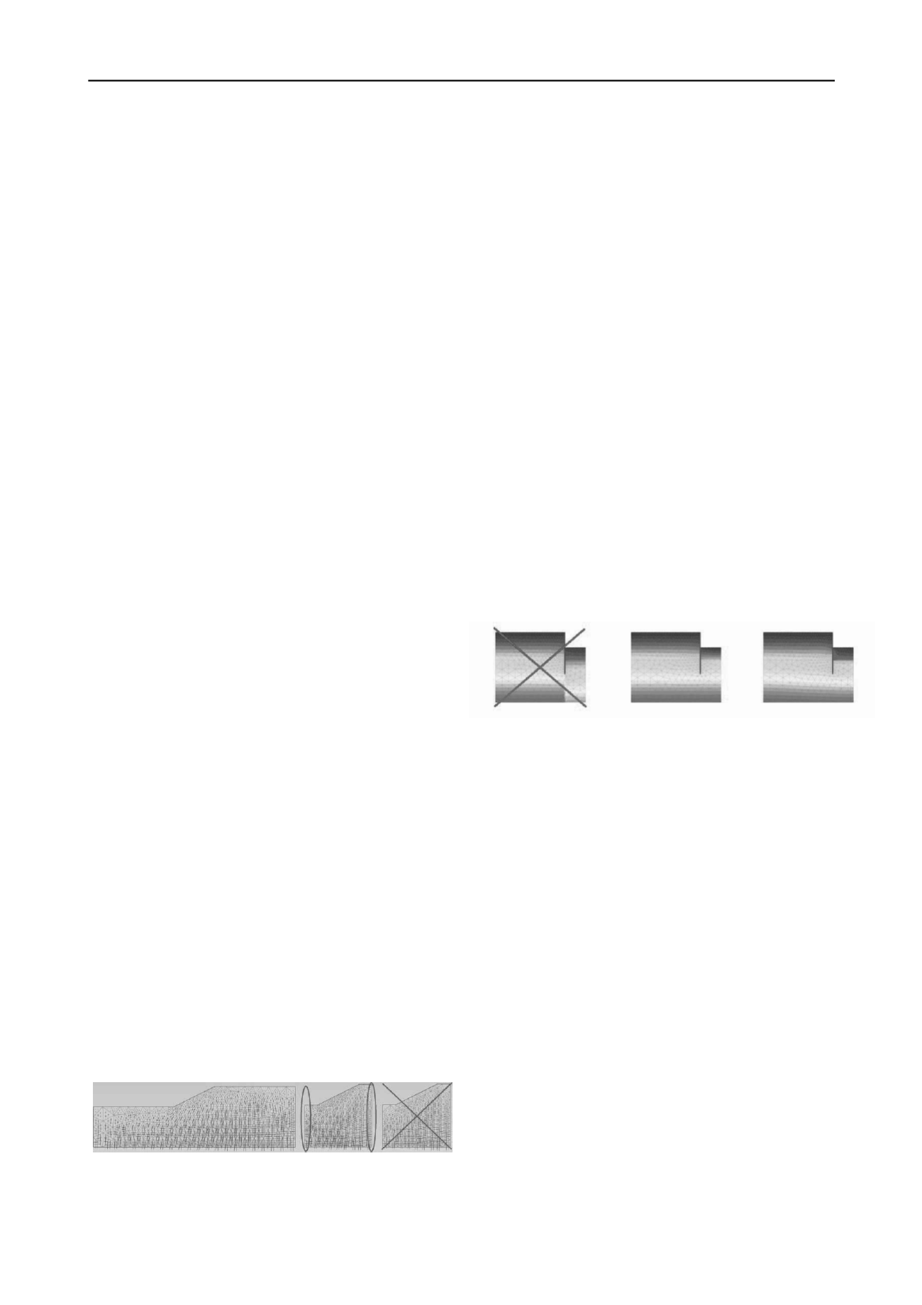
Figure 3. Generated pore water pressure distribution in an excavation
problem. a. Wrong distribution based on a ‘jump’ in the phreatic level
b. Improved distribution using interpolation between high and low head
under excavation c. Distribution based on groundwater flow calculation
(increased horizontal permeability)
Generated pore pressures should be validated against
measured pore pressure distributions in the field. It should be
validated that the pore pressure distribution is continuous and
‘smooth’; jumps are suspicious and are likely to be the result of
a wrong way of modelling.
4.4
Validation of (the accuracy of) results
The previous sections focused on essential components of the
model that are part of the modelling process. It also needs to be
validated that the finite element mesh is fine enough to produce
sufficiently accurate results. In case of doubt, the model can be
recalculated with a refined mesh. After the individual model
components and the model as a whole have been validated, and
numerical results have been obtained, there are various ways to
validate the results for the practical problem as considered. The
following methods can be used to validate the results of finite
element models:
Comparison with measurements (if the project is
already under construction)
Comparison with design charts.
Comparison with experience and common practice
Comparison with simplified models (e.g. reduced
dimensions; 1D vs. 2D or 2D vs. 3D)
Comparison with other software.
When considering a project in an urban environment,
experiences with previous projects in the neighbourhood can be
of great help in the validation of numerical models, since soil
conditions may be quite similar. Here, it should be realised what


