678
Proceedings of the 18
th
International Conference on Soil Mechanics and Geotechnical Engineering, Paris 2013
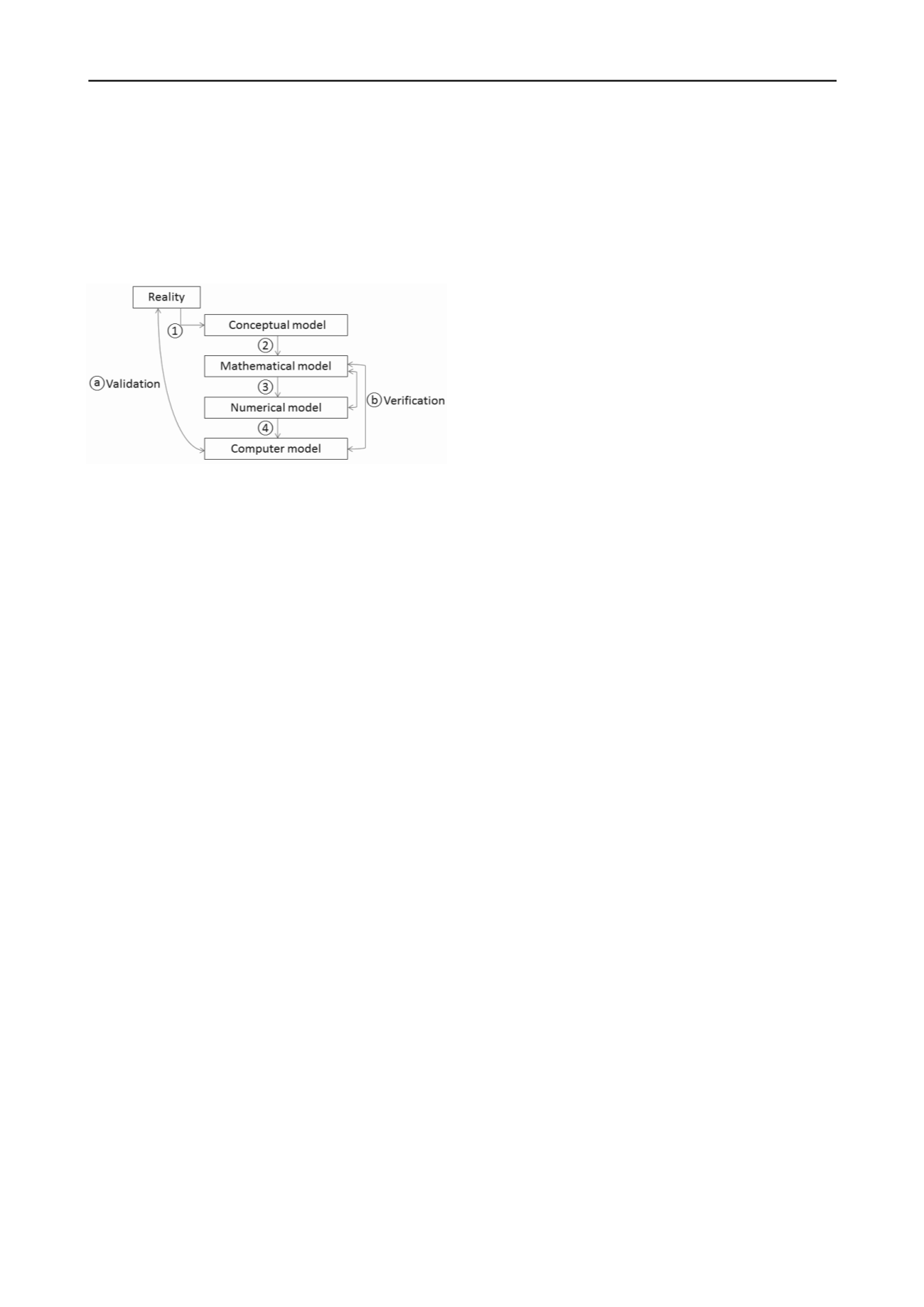
of validation and verification, the modelling process of Reality
is divided into four steps, as visualised in Figure 1.
In the first step (1) the complex physical reality is abstracted
into a simplified conceptual model. The main aim of this
modelling step is to determine the crucial processes and to
reformulate reality in a conceptual model by applying valid
simplifications such that the main phenomena as observed in
reality are retained in the model.
Figure 1. Visualisation of the modelling process from Reality to a
Computer model, and the position of Validation and Verification.
The second step (2) is the translation of the conceptual
model into a mathematical model. The mathematical model is
the mathematical formulation of the processes identified in the
conceptual model. Examples of mathematical models are the set
of partial differential equations describing equilibrium in a
continuum, and the constitutive model (stress-strain
relationship) describing the soil deformation behaviour.
The third step (3) is the translation of the mathematical
model into a numerical scheme. This generally requires a
discretisation of the problem in space and/or time.
The fourth step (4) is the implementation of the numerical
scheme into a computer model using a programming language
or using a modelling package.
The process to verify that a model or method has been
properly implemented in a computer program is called
Verification
(b).
Validation
, on the other hand, is the process to
make plausible that a computer model includes the essential
features for a real situation to be analysed and the results
obtained with the model are representative for the situation in
reality (a).
All the above steps may involve differences between the
computer model and reality. Considering existing dedicated
finite element software packages, it is the developers of such
packages who take most of the above steps and decide about the
mathematical formulation, the numerical schemes and the
implementation of models in their software. Therefore, the
responsibility of software developers mainly lies in the
verification of the software and the proper documentation of the
models and methods implemented in the software. For users of
existing software packages the division of the modelling process
into different steps is still relevant, although their position is
different. Starting from a practical engineering problem, users
first decide about the most relevant phenomena to be modelled
(conceptual model). By using an appropriate software package,
they select, apply and combine several of the implemented
models and methods to create a computer model for their
analysis. It is their responsibility to make plausible that the
model is a good representation of reality. Hence, the process of
validation is primarily their responsibility.
3 SOURCES OF DISCREPANCIES
In this chapter we will focus on the sources of discrepancies
between reality and finite element models. Since a numerical
model involves several components that may introduce
approximations and errors, it is necessary to identify each of
these components and their role in and contribution to the
discrepancy as a whole. Identifying possible individual
discrepancies may result in an improvement of the model and a
possible reduction of the overall modelling error. It may also
enable a quantification of the variation of design quantities by
considering parameter uncertainties and their possible value
ranges. Discrepancies may be divided into the following
categories: Simplifications, Modelling errors, Constitutive
models, Uncertainties, Software and Hardware issues and
Misinterpretation of results.
3.1
Simplifications
Simplifications are the results of modelling choices made by the
user of a software package. These are made in different parts of
the modelling process. Examples of simplifications are:
Geometrical simplifications
Selection of model boundaries
Simplifications in material behaviour
Simplifications in the construction process
For every simplification of reality the user needs to be aware
of its consequences.
3.2
Modelling errors
In addition to the aforementioned simplifications there is a
variety of other sources of modelling errors. Some of these can
be reduced when they are recognized; some can even be
completely avoided. Examples of modelling errors are:
Input errors
Discretisation errors (meshing)
Boundary conditions
Time integration
Tolerances (tolerated numerical errors)
Limitations in theories and methods (e.g. small-
deformation theory)
The process of validation can help to identify and quantify
such modelling errors.
3.3
Constitutive modelling
Probably the most important part of the numerical modelling
process is the selection of the constitutive model the
determination of the corresponding model parameters. Real soil
behaviour may involve several features that can be observed
and measured in lab tests and in situ, but which are still difficult
to capture in a homogenized continuum formulation. Apart from
the limitations of the constitituve models themselves with
respect to real soil behaviour, some typical issues related with
different aspects of constitutive modelling are highlighted here:
Non-uniqueness related to non-associated plasticity and
strain-softening
Undrained behaviour
Unsaturated behaviour
Software developers need to properly document the
constitutive models used in their software, whereas users need
to be aware of the typical issues related to constitutive
modelling in general and the possibilities and limitations of the
models used in their applications.
3.4
Uncertainties
In the aforementioned sections it was assumed that the
behaviour in reality would be fully known and that modelling
discrepancies are the result of the modelling process only. The
fact is that there are many aspects in a real project that are not
completely known (yet) or which cannot be measured
accurately. In other words, there are uncertainties about what
we need to model precisely to reflect the real construction
process and the conditions that are applied to the real structure
during its lifetime. Examples of uncertainties are:
Lack of soil data


