690
Proceedings of the 18
th
International Conference on Soil Mechanics and Geotechnical Engineering, Paris 2013
Model ground
(Aluminium bars)
Retaining blocks
Stopper stand
Stopper barrier
Wall blocks after collapse
6 5
12 4 3
5cm
b) Computed results
Wall blocks after collapse
5cm
6 5
12 4 3
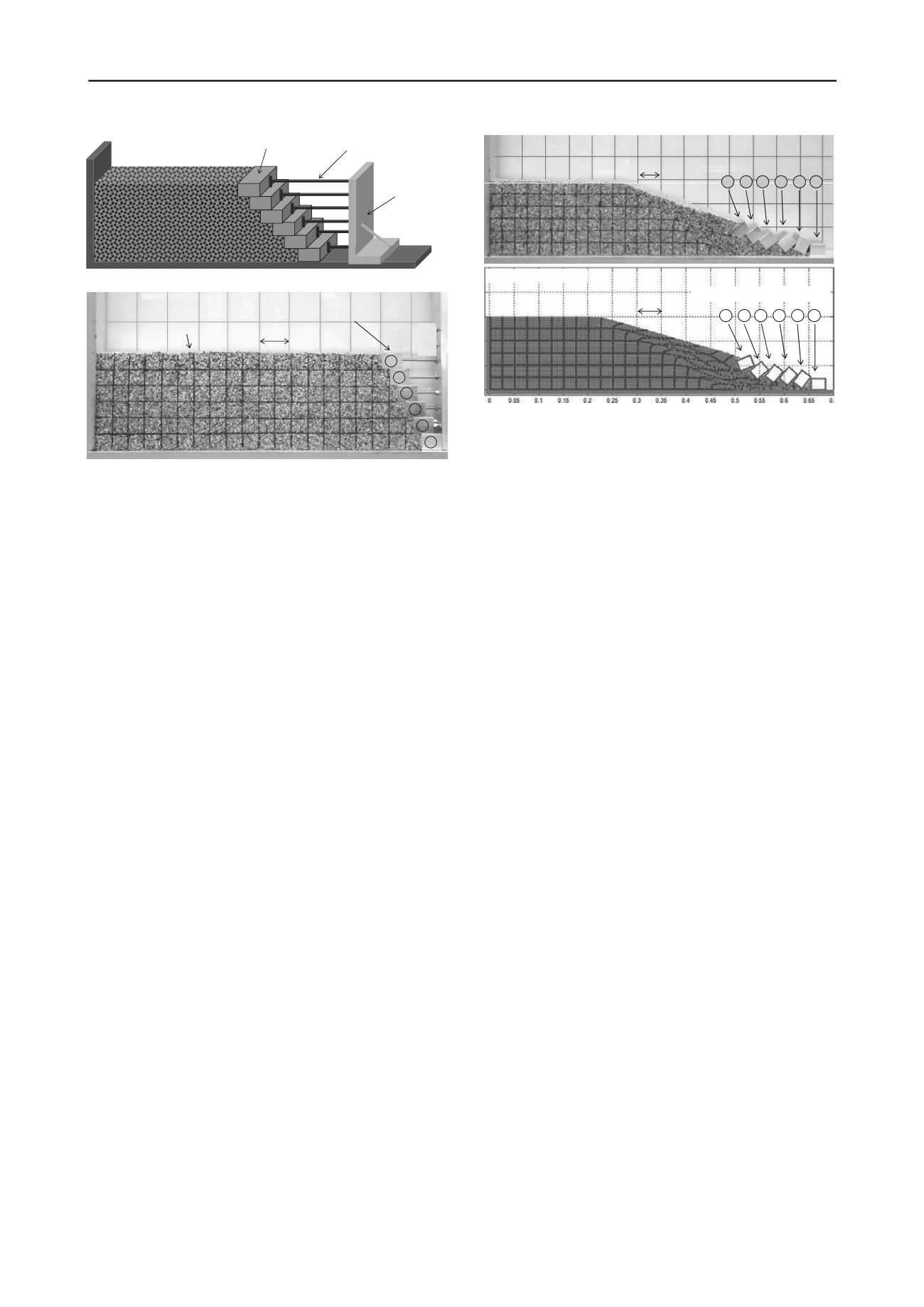
a) Experimental results
Figure 1. Schematic diagram of 2D experimental model.
Model ground
(Aluminium bars)
Retaining blocks
5cm
2
1
5
3
4
6
Figure 3. Comparison between experiment and SPH simulation.
5 CONCLUSION AND FUTURE WORKS
Figure 2. Initial setting condition of the model test.
In addition, tests were conducted to measure static friction
coefficients. It was found that the static friction (
) between
retaining wall blocks is
0.62, between wall block and the
bottom wall boundary is
0.60, and between the retaining wall
block and model ground is
0.56. The experiment series were
conducted starting from one block and then gradually increasing
the number of blocks in the retaining wall system until the
retaining wall collapsed. It was observed that the retaining wall
system collapsed when reaching 6 blocks. Accordingly, a
numerical model consisting of 6 retaining wall blocks was
conducted for the benchmark study.
4 RESULT AND DISCUSSION
The model test shown in Figure 2 was simulated using 11,304
SPH particles arranged in a rectangular lattice with an initial
separation of 0.25cm. Rigid blocks were created by placing
boundary particles uniformly around the boundary at a constant
distance. In order to simulate the smooth surface, half of particle
spacing was chosen for the rigid body boundary particles.
Model ground parameters including elastic modulus
E
=1.5MPa,
Poisson’s ratio
= 0.3, friction angle
= 19.8
o
, dilatant angle
= 0
o
, and cohesion
c
= 0kPa were taken similar to those used in
Bui et al. (2008). The unit weight of the ground model is
s
=
23kN/m
3
. The friction coefficients between the rigid blocks,
between the block and the bases of the wall boundary, and
between the block and the ground model were taken to be
similar to those measured in the experiment as mentioned in
Section 3. The boundary conditions for the model ground are
restrained with a free-slip boundary at the lateral boundaries and
fixed in both directions at the base.
This paper presented a novel numerical approach for simulation
of large deformation and post-failure of segmental retaining
wall. It was shown that the proposed method provides good
agreement with the experimental results. The most significant
advantage of the new method is that the complete degrees-of-
freedom of the retaining wall blocks, which could not be
simulated using traditional numerical approaches, can now be
simulated in the proposed numerical framework. Large
deformation and post-failure behaviour of geomaterials can also
be readily simulated. To broaden the application of the proposed
numerical approach, further implementations such as coupling
with geo-grid reinforcement, modelling seismic earthquake
loading, and bonding between blocks should be considered in
the future. Full extension to three-dimension code would yield
significant benefits to gain further insights into the mechanisms
of SWR.
6 REFERENCES
Bui H.H, Sako K, Fukagawa R. 2007. Numerical simulation of soil-
water interaction using smoothed particle hydrodynamics (SPH)
method.
Journal of Terramechanics
,
44
, 339-346.
Bui H.H, Fukagawa R, Sako K. and Ohno S. 2008. Lagrangian mesh-
free particle method (SPH) for large deformation and post-failure of
geomaterials using elastic-plastic soil constitutive model,
International Journal for Numerical and Analytical Methods in
Geomechanics
,
32
, 1537-1570.
Bui H.H, Fukagawa R, and Sako K. 2011. Slope stability analysis and
discontinuous slope failure simulation by elasto-plastic smoothed
particle hydrodynamics (SPH).
Géotechnique
,
61
, 565-574.
Figure 3 shows the comparison between the experiment and
the computation. It can be seen that, because the complete
degrees-of-freedom of the rigid body was taken into
consideration, the computed result could predict fairly well the
behaviour of all rigid blocks observed in the experiment after
the SWR system collapsed. The final run-out distance of Block
No.1 in the simulation is 67.5cm from the left-most solid
boundary. This result is in very good agreement with that
observed in experiment (
68cm). It is suggested that the
proposed soft contact model could be applied to simulate the
soil-structure interaction in the SRW system. However, further
refinement of the contact model should be considered to provide
more accurate prediction of the retaining wall blocks and the
model ground as the simulation results showed a slight over-
prediction of the failure zone observed in the experiment.
Bui H.H. and Fukagawa R. 2012. An improvement of SPH for saturated
soils and its application to investigate the mechanisms of
embankment failure: Case of hydrostatic pore-water pressure,
International Journal for Numerical and Analytical Methods in
Geomechanics
. doi: 10.1002/nag.1084.
Cundall P.A, Struck ODL. 1979. A discrete numerical model for
granular assemblies.
Géotechnique
,
29
, 47-65.
Gingold R.A., Monaghan J.J. 1977. Smoothed particle hydrodynamics:
Theory and application to non-spherical stars.
Mon. Not. Roy.
Astron. Soc.
,
181
: 375-389.
Monaghan J.J. 2003. SPH elastic dynamics.
Computer Methods in
Applied Mechanics and Engineering,
190
, 6641-6662.
Monaghan J.J, Lattanzio J.C. 1985. A refined particle method for
astrophysical problems.
Astronomic & Astrophysics
,
149
,135-143.
Pastor M., Haddad B., Sorbino G., Cuomo S., Drempetic V. 2009. A
depth-integrated, coupled SPH model for flow-like landslides and
related phenomena.
International Journal for Numerical and
Analytical Methods in Geomechanics
,
33
, 143-172.
Shi G.H. 1988. Discontinuous deformation analysis: a new numerical
model for the static and dynamics of block systems. Ph.D. thesis,
University of California, Berkeley.


