582
Proceedings of the 18
th
International Conference on Soil Mechanics and Geotechnical Engineering, Paris 2013
7
CONCLUSIONS
Soil improvement described in this paper involved stone
columns installed below each tank. The gravel material pressed
into the soft soil is equivalent to a layer of about 30 cm in
thickness. Since the geodetic surveys showed negligible soil
upheaval (a few millimetres), it can be concluded that the soil
improvement prevented equivalent settlement of 30 cm.
The hydro test showed, as demonstrated in the case of Tank
A-2507, that total settlements are relatively small, i.e. smaller
than estimated by calculation (Figure 6).
For the purpose of comparing actual settlements with those
given in behaviour criteria, the settlements of the tank bottoms
are shown so that displacements corresponding to a rigid body
rotation are given separately from displacements resulting from
non-planar differential settlement. Figure 3 illustrates that the
bedding was mostly displaced as a rigid body, while non-planar
differential settlement was slight. For this reason, it is sure to
say that maximum values of the settlements and their shapes are
within the values required by the relevant standard (Figure 4).
0
20
40
60
80
100
120
140
160
180
200
load [kPa]
-22.0
-20.0
-18.0
-16.0
-14.0
-12.0
-10.0
-8.0
-6.0
-4.0
-2.0
0.0
settlement
[cm]
hydro test for tank A-2507
tank center - measured
tank periphery - measured
tank center - Plaxis - calculated
tank periphery - Plaxis - calculated
Figure 6. A comparison of measured and calculated results of
settlements obtained from the hydro test on Tank A-2507.
It was found that the settlements, after the tank had been
emptied, were smaller although they had the same shape. This
proves that the deformations after tank emptying are mostly
elastic (Figure 4). As tank loads by crude oil are less than those
by water, it is expected that subsequent displacements at
operating load will be less than those recorded in hydro tests,
and that no further non-planar differential settlement of the tank
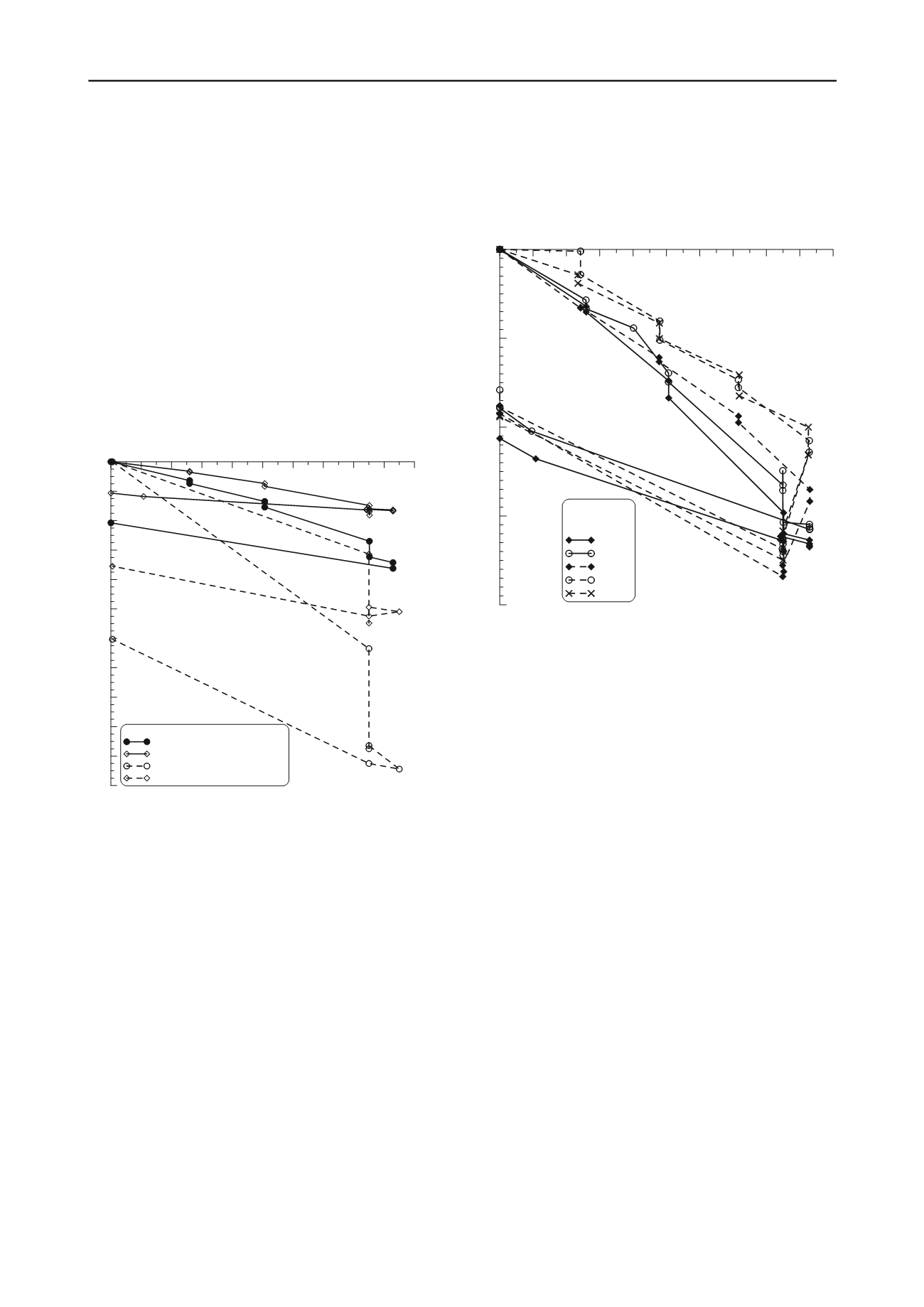
bedding will occur. The same goes for the other four tanks
(Figure 7). The diagram of the settlements of all five tanks
shows that such settlements are about the same when the tanks
are subjected to the same load. As this is normally expected in
the case of horizontally stratified soil, this is proof of proper and
correct measurement of displacement.
As seen in Figure 6, the settlements obtained by calculation
were significantly greater than those measured. An explanation
for different values of settlements should be thoroughly
investigated in further numerical analysis which will take into
consideration the fact that columns and soil act together as
recommended in Ambily and Gandhi (2004).
In the case of the Sisak tanks, the hydro tests proved correct
functioning of the floating roofs, watertightness of the shells
and bottoms, and rigidity of the foundation structure for all
tanks.
The strictly applied procedures regarding soil investigation,
design, hydro test and exploitation ensured safety in execution
and further use. Considering the safety risks and loss of
investment in case of non-allowable differential settlements of
the soil, it is clearly understandable, yet in some cases
disregarded, why such procedures must be applied.
The data collected about the behaviour of the tanks during
the hydro tests were well documented and could be used to
improve design of tanks.
0
20
40
60
80
100
120
140
160
180
200
load [kPa]
-4.0
-3.0
-2.0
-1.0
0.0
settlement [cm]
hydro test -
tank periphery
- measured
A-2507
A-2508
A-2509
A-2510
A-2511
Figure 7. Total settlements of tank perimeters during hydro tests
performed on all five tanks
8
ACKNOWLEDGEMENTS
The writers particularly wish to thank Z. Korica and M. Bago
for their support and assistance.
9
REFERENCES
Ambily, A.P.& Gandhi, S.R. 2004. Analysis of hydro test results for
steel tank on stone column improved ground. Proceedings of the
Indian Geotechnical Conference held at NIT Warangal, 420-423.
API-650: American Petroleum Institute (API) standard 650: ”Welded
tanks for oil storage”.
API-653: American Petroleum Institute (API) standard 653: “Tank
Inspection, Repair, Alteration, and Reconstruction”
Bell, R.A. & Iwakiri, J. 1980. Settlement comparison used in tank-
failure study. Journal of the Geotechnical Engineering Division
106, GT2, 153-169.
Berardi, R. & Lancellotta, R. 2002. Yielding from field behavior and its
influence on oil tank settlements. Journal of geotechnical and
geoenvironmental engineering 5, 404-415.
EN 14015:2004, Specification for the design and manufacture of site
built, vertical, cylindrical, flat-bottomed, above ground, welded,
steel tanks for the storage of liquids at ambient temperature and
above
Marr W.A., Ramos J.A. & Lambe T.W. 1982. Criteria for settlement of
tanks. Journal of the Geotechnical Engineering Division 108, GT8,
1017-1039.
Raju, V.R., Hari Krishna, R. and Wegner, R. 2004. Ground
improvement using Vibro Replacement in Asia 1994 to 2004 – a 10
year review, Proceedings of 5th Int. Conf. on Ground Improvement
Techniques, Kuala Lumpur, Malaysia.


