581
Technical Committee 102 /
Comité technique 102
been completed, visual inspection and measurements of
settlements and deformations of the steel structure were made.
The next phase of the hydro test could begin only after the
analysis of the results of measurements obtained from a
previous one had been made.
Monitoring of each tank settlement involved geodetic
surveys and measurement of settlements by a horizontal
inclinometer. The geodetic surveys included 24 points on the
outside perimeter of the foundation and one point on each of six
manholes allowing access to horizontal inclinometer pipes (HI).
Settlement measurements were made in three 100-m long pipes
running below the tank centre and horizontally declined by 60
.
The manholes were located eight meters outside of the
foundation perimeter.
A monitoring programme was planned and carried out in a
similar manner as described in the paper by Berardi and
Lancellotta (2002).
6.2
Hydro test results
By way of illustration, the results of settlements obtained from
the hydro test carried out on Tank A-2507 are given. Figure 2
shows time history of tank and bund filling and emptying
together with the graphs showing averaged settlements of HI
pipes at manholes HI, points on the foundation perimeter and
centre.
-8
-7
-6
-5
-4
-3
-2
-1
0
settlement [cm]
manhole R=47,5 m
tank periphery - R=39,5 m
tank center R= 0 m
27/02/10
06/03/10
13/03/10
20/03/10
27/03/10
03/04/10
10/04/10
17/04/10
24/04/10
01/05/10
08/05/10
15/05/10
22/05/10
29/05/10
05/06/10
date [dd/mm/yy]
0
2
4
6
8
10
12
14
16
18
20
water level [m]
hydro test for
tank A-2507
tank
bund wall
Figure 2 Time history of the hydro test performed on Tank A-2507
According to settlement criteria (Marr et al 1982), the design
defined allowable total and differential settlements for different
settlement patterns. Thus, during the hydro test, the allowable
total settlement of the tank perimeter and tank centre were 15
cm and 31 cm respectively. In a calculation, they were
estimated to be 11 cm and 19,5 cm respectively. However, the
results of measurement obtained for such settlements as shown
on the graph were 3,6 cm and 7,2 cm respectively.
Figure 3 shows total settlements of the tank perimeter for the
two representative phases of the hydro tests in which the largest
settlements occurred at the highest loads. In the third phase, i.e.
when the tank was emptied, permanent (plastic) deformations
occurred.
0
50
100
150
200
250
tank perimeter [m]
-4.5
-4.0
-3.5
-3.0
-2.5
-2.0
-1.5
-1.0
total
settlement
[cm]
hydro test for tank A-2507
date / water level
26.3.2010 tank=17 m; bund=17m
07.04.2010 tank=19 m; bund=0m
07.06.2010 tank=0 m; bund=0 m
plane of rigid tilt
Figure 3 Total settlements of the tank perimeter occurred during the
hydro test on Tank A-2507
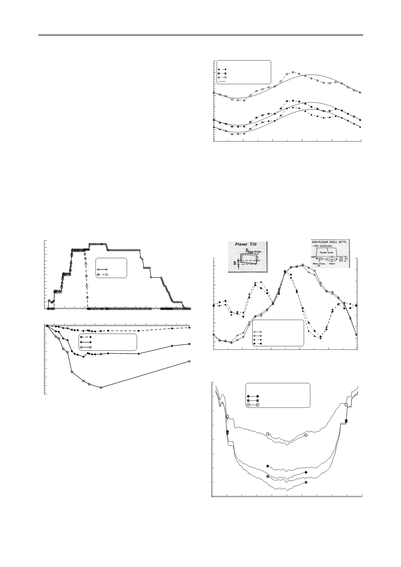
Figure 4 illustrates the two phases in which the largest
differential settlements of tank perimeter at the highest load
occurred as well as the phase following tank emptying in which
permanent (plastic) deformations occurred.
Design allowable differential settlements for the cases of
planar tilt settlement and non-planar differential settlement was
44 cm and 0,8 cm respectively. The planar tilt settlement and
non-planar differential settlement obtained by calculation were
1,3 cm and 0,34 cm respectively. The results of measurement
obtained for such settlements were 1,0 cm and 0,32 cm
respectively.
0
50
100
150
200
250
tank perimeter [m]
-0.4
-0.3
-0.2
-0.1
0.0
0.1
0.2
0.3
0.4
non-planar
differential settlement [cm]
-1.0
-0.5
0.0
0.5
1.0
planar tilt differential
settlement [cm]
hydro test for tank A-2507
26.3.2010 tank=17 m; bund=17m
07.6.2010 tank=0 m; bund=0m
planar diff. settl. 26.3.2010
planar diff. settl. 07.06.2010
non-planar diff. settl. 26.3.2010
non-planar diff. settl. 07.06.2010
Figure 4 Differential settlements at the perimeter of Tank A-2507
Figure 5 shows total settlements for the three representative
phases of the hydro test measured by horizontal inclinometer.
-50
-40
-30
-20
-10
0
10
20
30
40
50
tank diameter [m]
-8
-7
-6
-5
-4
-3
-2
-1
0
total settlement [cm]
hydro test for tank A-2507
horizontal inclinometers along tank diameter
date / water level
26.3.2010 tank=17 m; bund=17m
07.04.2010 tank=19 m; bund=0m
07.06.2010 tank=0 m; bund=0 m
manhole GR-28
tank periphery GR-13
tank center
manhole GR-25
tank periphery GR-1
Figure 5 Total settlements of Tank A-2507 (cross-section)


