195
Technical Committee 101 - Session I /
Comité technique 101 - Session I
Proceedings of the 18
th
International Conference on Soil Mechanics and Geotechnical Engineering, Paris 2013
of the analytical solutions for consolidation under radial
drainage are based on the assumption that only vertical
compression occurs. A new physical consolidation model test
under plane strain condition, which enables the observation of
the deformation of a specimen through digital image analysis,
and the measurement of the total vertical stress as well as the
pore water pressures, is developed by Kim et al. (2013). A
schematic view of the apparatus is shown in Figure 10.
Consolidation tests of reconstituted kaolin samples (150 mm
height, 140 mm width, and 40 mm thickness) were performed
using the new consolidation apparatus under radial drainage,
along with test under vertical drainage. Radial deformations as
well as vertical deformations during consolidation were
monitored and compared for the two different drainage
conditions. Significant horizontal displacements are occurring
during the early stages of the consolidation process, whereas
during the intermediate stage, only minor horizontal
displacements are identified. The horizontal displacements are
higher near the boundaries and this induces uneven void ratio
distribution at the end of consolidation. Meanwhile, for the
vertical drainage, only minor variations of the horizontal
displacements inferior of 0.006 mm were observed.
Figure 10. Schematic view of the consolidation test apparatus (Kim et
al. 2013)
A laboratory apparatus for axi-symmetric electro-osmotic
consolidation of cylindrical samples of 37.6cm diameter and
20cm height is developed by Hu et al. (2013) with capabilities
of measuring the electrical voltage, soil mass displacement,
water discharge, and electrical current parameters (Figure 11).
While tests on kaolin clay showed non-linear variation of soil
parameters and complex coupling effects between water flow,
soil deformation and electrical properties, a theoretical model
that
integrates Biot’s consolidation equation with the electro
-
osmotic flow and the equation for an electric field is proposed.
Figure 12 shows the comparison of the surface settlement at one
location between the numerical results and the experiment data.
The simulations of the model with variable electrical
conductivity agree better with the experimental data than those
of the model with constant electrical conductivity.
Figure 11. Electro-osmotic apparatus (Hu et al. 2013)
Figure 12. Comparison of the settlement between the numerical
results (two models) and recorded data (Hu et al. 2013).
Compression properties of Swedish fine-grained sulphide
clay soils are explored by Westerberg and Andersson (2013)
through the monitoring and analysis of the long-term response
of two instrumented real scale test embankments. Actually, the
predicted settlements of a construction founded on sulphide
soils deviates significantly from those measured in situ, and
normally the predicted settlements are too small. In sulphide
soils, the structure is often relatively porous and the voids
between the mineral grains and clay particles are filled with
pore water, organic material and iron sulphide. Field
investigations of the properties of the sulphide soil were
performed by cone penetration tests, field vane tests and
Swedish piston sampling and an extensive program of
laboratory investigation, in oedometer, both by incremental
loading and constant rate of strain, creep tests, permeability as
well as undrained direct simple shear tests, were conducted for
the determination of compression and strength properties. Very
good agreement between data given by different field
instrumentations is reported.
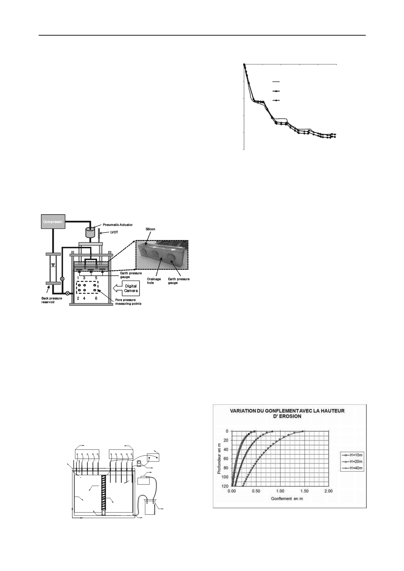
The heave rebound strain prediction of overconsolidated
soils represents an important engineering design issue since the
development of major road infrastructures that involve deep
excavations and trenches. Based on the use of simple oedometer
tests combined with an analysis of stress paths approached by
Ylight model (Leroueil, Magnan & Tavenas, 1985), Petit et al.
(2013) present a quantification method of those heave rebound
strains. The results of the calculations of the heave rebound over
a 120m deep clay deposit for three excavation depths of 10, 20
and 40m are shown in the Figure 13. The estimations show that
the elastic rebound are relatively small, between 0.01 and
0.02m.
Figure 13. The profile of the heave rebound for three different
excavation depths (Petit et al. 2013).
Top cap
moisture
trap
z
r
Soil Sample
displacement
sensor
Voltage
sensor
Cathode
drain hole
Vertical drain
Anode
Data acquisition instrument
power source
Vacuum pump
Outlet of water
ammeter
-0.025
-0.02
-0.015
-0.01
-0.005
0
0
20
40
60
80
100
t
/h
Experiment data
Numerical result:variable parameters
Numerical result:constant parameters
Settlement (m)
Earth pressure
gauge
Pore pressure
measuring points
Back pressure
reservoir
LVDT
Digital
Camera
PneumaticActuator
Compressor
Silicon
Earth pressure
gauge
1 3 5
2 4 6
Drainage
hole


