186
Proceedings of the 18
th
International Conference on Soil Mechanics and Geotechnical Engineering, Paris 2013
Proceedings of the 18
th
International Conference on Soil Mechanics and Geotechnical Engineering, Paris 2013
Figure 8. Preparation to casting the reinforced concrete struts in a ‘top
down’ section of the project.
5 CONSTRUCTION BY MINING
Of all the different methods used on this project, the three
mining sections were by far the most challenging. At Beach
Road, two mined tunnels were constructed, the larger one for
the railway and a second, smaller, pedestrian tunnel for a future
development link. The large cross section of the rail tunnel at
Beach Road was necessary as the crossover was situated at this
location between the end of the bored tunnel section and the
station platforms. At Queen Street a similar mined tunnel was
required for the rail albeit with a smaller cross section. The
mined tunnel below the existing Bugis Station was an entirely
different proposition. Fully 80m long it stretched below the
entrance structures and the central platform section with the
operating railway running for the whole duration of the works.
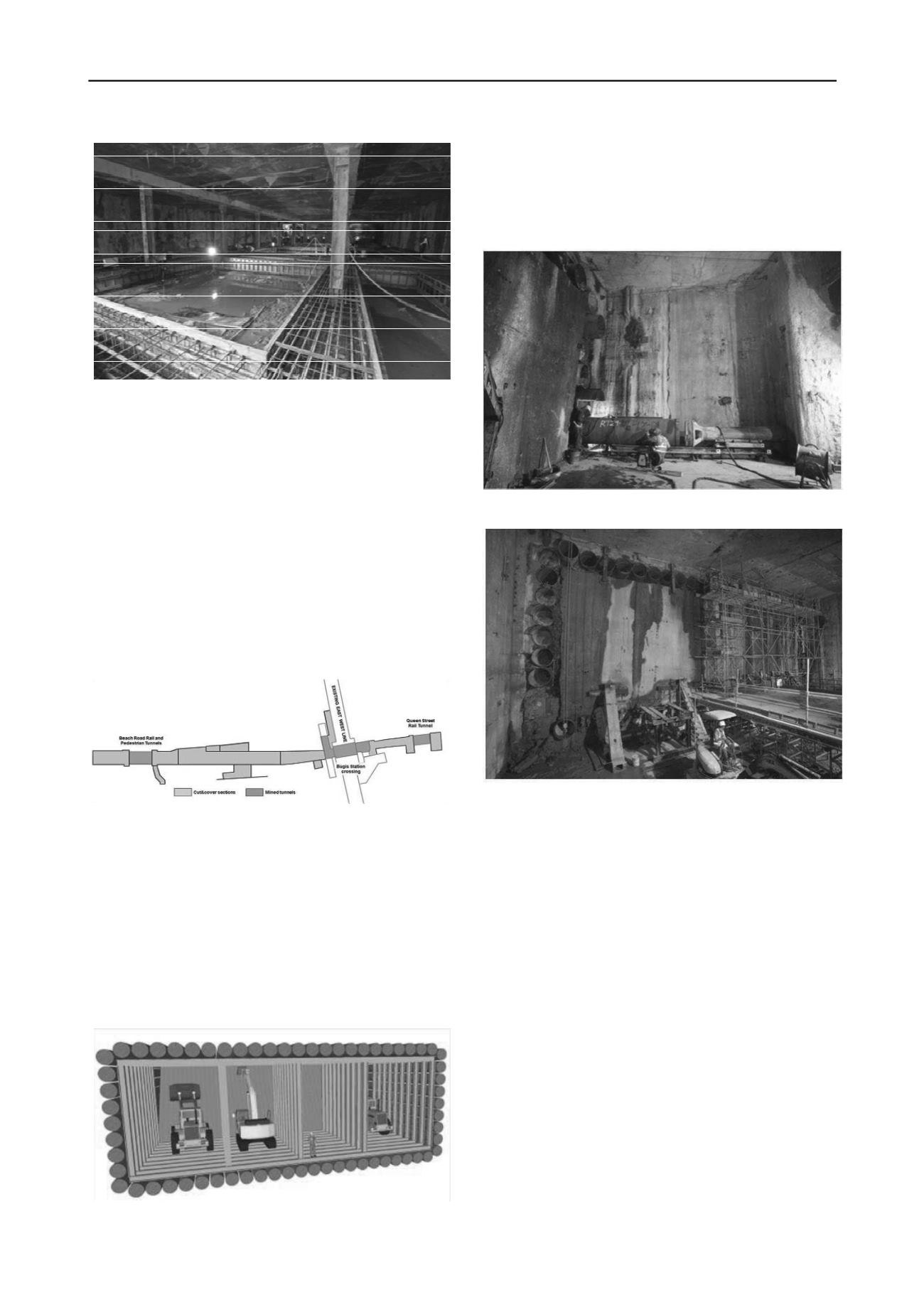
Figure 9. C903 Bugis station and associated tunnels layout.
5.1.
Beach Road and Queen Street tunnels
These two lengths of 30m and 40m tunnels of a large sectional
area (7.5mx22m and 7mx15m) are entirely excavated in the
very soft marine clay layer and require extensive preliminary
works. To prevent any instability during the excavation, the
whole area was improved by jet grouting. Deep columns
(>30m) were installed from the surface for a total of 29,000m3.
The retaining structure was made of horizontal pipe piles
(600mm and 900mm diameters) installed from the cut and cover
areas by pipe ramming method.
Figure 10. Schematic view of the excavation method for Beach Road
and Queen Street tunnels.
The diaphragm wall was opened by stitch coring to allow the
pipe pile installation. At 30m below ground level, the risk of
water seepage was high and at some locations, additional
grouting was carried out to ensure these openings were
watertight. The cut section of wall was supported by steel
propping in the temporary stage.
Figure 11. Setting up and welding – Beach Road rail tunnel.
Figure 12. Temporary propping to support diaphragm wall.
The pipes were driven with two types of hammers operated
by compressed air. Due to the restricted working space and the
ongoing structural works in the vicinity, the pipes were installed
in short sections and welded together. Depending on the area,
Soletanche Bachy were able to use either 4m or 6m lengths of
pipe. In some areas where access and the working area were
severely restricted (40m long pipe pile installation for the
Central Mining through an additional small shaft), the hammer
was installed directly within the pipe to minimize the overall
length.
Even with this powerful tool, hardened soil by Jet Grouting
or obstructions caused refusal of the pipe driving. In such
instances an auger was used to clean the pipe before resuming
pipe ramming. Once completed, the pipes were fully cleaned
out using the auger and the pipes cast with self-compacting
concrete. For the last stage, the excavation of the tunnels was
carried out using traditional methods with the installation of
steel frames at regular intervals to support the pipes. At peak
production 70 welders were required for pipe and steel frames
installation.
5.2.
Mining under existing Bugis Station
By comparison to the Beach Road and Queen Street tunnels, the
Bugis Station mined tunnel posed different problems and
represented the most sensitive part of the overall project.
Tubular piles (600mm and 900mm diameter) acting as retaining


