3416
Proceedings of the 18
th
International Conference on Soil Mechanics and Geotechnical Engineering, Paris 2013
Proceedings of the 18
th
International Conference on Soil Mechanics and Geotechnical Engineering, Paris 2013
(McCartney et al., 2010). Countries such as China, Ireland and
Japan are also experiencing an increased interest in the use of
thermo-active piles (Hamada et al., 2007, Gao et al., 2008,
Hemmingway and Long, 2011, Jalaluddin et al., 2011).
3 ENERGY PILE FIELD TEST
3.1
Background
The study conducted at Monash University is part of an
international research effort aimed at obtaining a much better
understanding of the thermo-mechanical effect on piles with the
view of reducing the conservative approach taken so far in the
design of energy piles. The study involves evaluation of the
thermo-mechanical behaviour of soils, the thermal capacity of
the pile, the built structure heat balance, soil thermal properties
and influence of heat transfer on pile load capacity and shaft
resistance. This paper reports on the pile field test undertaken at
the Clayton campus of Monash University, Victoria, Australia.
3.2
Site temperature profile
To efficiently operate a heat exchanger pile system, the ground
temperature needs to be warmer than the air temperature in
winter and cooler than the air temperature during summer. This
requires a ground with relatively constant temperature and
knowledge of the magnitude of ground temperature changes for
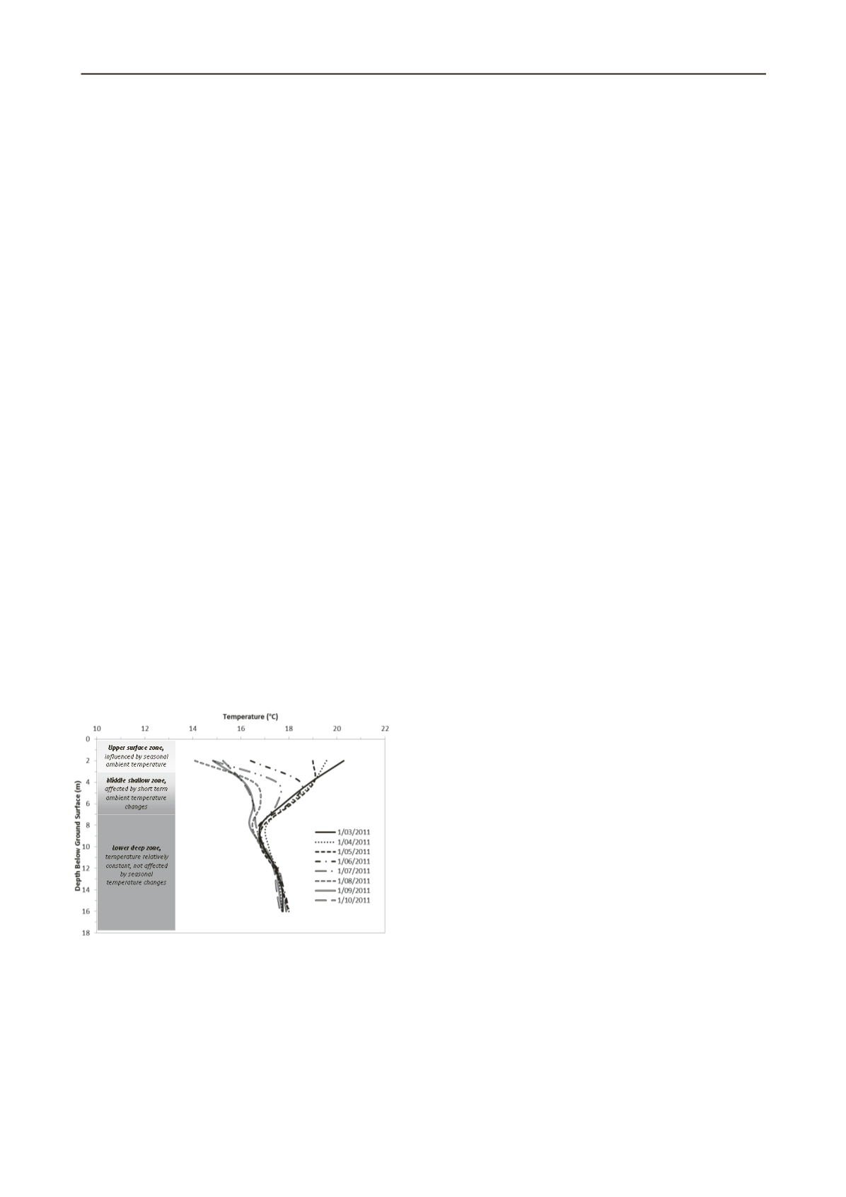
this system to operate efficiently. In-situ temperature profiling
was conducted at the pile field test site. The site consists of 3 m
thick clayey fill overlying Brighton Group materials from 3 m
onward. The Brighton group consists mostly of fine to coarse
very dense clayey sands and sands. Monitoring of ground
temperature variation (Figure 1) indicates that the temperature
of the surface zone (approximately 2 m below ground surface)
and, to a lesser extent, that of the shallow zone (2 to 6 m) are
influenced by short term ambient temperature changes. These
variations begin to diminish upon reaching a depth greater than
that of the shallow zone. Beyond 8 m (deep zone) temperatures
are relatively constant (17-18 ºC) and are unaffected by seasonal
temperatures changes making them suitable for heat exchanger
pile systems.
Figure 1. Typical ground temperature variation with depth, recorded at
Clayton, Australia.
3.3
Energy pile setup
The Monash field heat exchanger or energy pile was installed in
December 2010. It is a 600 mm diameter bored pile drilled to a
depth of 16.1 m in Brighton Group materials. Groundwater was
not observed during the installation process. Two levels of
Osterberg cells (O-cells) were installed at 10 m and 14.5 m
depth. By using two O-Cell levels, an accurate independent
measurement can be taken for the material within the
intermediate sections of the pile by observing the reaction of the
relevant strain and displacement gauges with or without thermal
loading. The use of O-cell also eliminates health and safety and
other constraints associated with conventional static testing
systems such as kentledge or anchor piles. The testing and
monitoring equipment installed within the pile consisted of the
following:
•
Three loops of HDPE pipe (25 mm OD) attached to the
pile cage, to 14.2 m, to circulate the heating transfer fluid.
•
10 vibrating wire strain gauges installed between the
two O-cells levels and 6 vibrating wire strain gauges installed
above the upper O-cell level.
•
12 vibrating wire displacement transducers installed
within the pile to measure O-cell and pile movements.
•
All vibrating wire instrumentations were fitted with a
thermistor, and temperature of the concrete monitored at various
levels.
Two boreholes were installed at a distance of 0.5 m and
2.0 m to the energy test pile, thermocouples were installed at
2 m intervals in each borehole to profile the temperature
changes with depth and measure ground temperature during
thermal loading.
4 FIELD PILE TEST RESULTS
4.1
Thermal properties
The ground thermal properties are paramount for an accurate
design of a geothermal energy installation especially when it
comes to sizing and costing the system. In this respect, in-situ
ground thermal conductivity, pile thermal resistance and
undisturbed ground temperature are key parameters for a
successful design. The most important parameter required to
optimise the design of energy piles or boreholes ground heat
exchangers is the thermal conductivity of the ground (heat
exchanger system and the surrounding soils). For the
preliminary design of complex energy foundations or the
detailed design of standard geothermal systems, sufficient
accuracy of ground thermal properties can be obtained from
field thermal response or laboratory testing. The thermal
conductivity of the ground, which is directly relevant to the
temperature-depth relationship, is sensitive to the local on-site
geology and affected by its mineralogical composition, density,
pore fluid and degree of saturation (Abuel-Naga et al., 2008,
2009). As a result, there is no constant depth at which all
geothermal energy systems should be installed. Rather, factors
such as local geology, climate and even surface cover must be
considered in order to help determine a depth at which the
ground temperature is relatively unaffected by seasonal
temperature changes and to specify the required length of heat
exchangers needed for the pile foundation.
Some of the thermal property parameters can be determined
in laboratory tests but inclusion of site specific conditions such
as groundwater flow and in-situ stresses are difficult to
implement. Currently there is no testing standard available to
conduct in-situ thermal conductivity of energy piles and assess
their thermal resistance. However, the American Society of
Heating, Refrigeration and Air Conditioning (ASHRAE)
published a set of recommended procedures for undertaking
formation thermal conductivity tests for geothermal applications
(ASHRAE 1118-TRP). This procedure is popular with the
borehole ground loop systems. However, the diameter of a
borehole compared to a pile is a lot smaller and the number of
piping loops is also lower.
Three Thermal Response Tests (TRTs) were carried out
during the heating periods of the field testing program. The
TRTs were carried out utilising a TRT unit consisting of a
computerised logging system, control box, water pump, heating
elements and a water reservoir. There is one outlet and one
inlet on the TRT Unit. One TRT was carried out by circulating


