3424
Proceedings of the 18
th
International Conference on Soil Mechanics and Geotechnical Engineering, Paris 2013
The smouldering leads to high temperatures inside the dump.
These high temperatures imply a high energy potential, which
isn’t utilized until now. For determining the possible heat output
from a smouldering a pilot plant on a mining dump in the ‘Ruhr
Area’ in the western part of Germany has been operated over
three years. An overview of the dump and the pilot plant is
shown in Figure 1.
Three heat exchanging fields have been installed. Each field
consists of a borehole heat exchangers (BHE) - designed as a
coaxial probe – and five temperature measuring gauges,
arranged in a semicircle around the BHE. Additional
information on the plant can be found in Kürten et al. (2010).
The heat exchanging fields were placed in a known Hot Spot
(HS 6 in Figure 1). The maximum temperatures in each field
varied between 75 °C (field 1) and 430 °C (field 2). The
maximum values occurred in about 15m depth. So, the high
energy potential of the dump can be confirmed.
Several Thermal Response Tests (determining the short-term
behaviour of the plant, see e.g. Gehlin 2002) as well as long-
term test were carried out. Additional, numerical simulations
and analytical investigations were performed for estimating the
main influencing parameters for the heat output. It could be
shown, that a total heat output for the plant of 8kW could be
achieved (Kürten et al. 2010). This corresponds to a heat
requirement of two single family houses in Germany,
approximately
.
3 THERMO-ACTIVE SEAL PANELS
Based on the principle of thermo-active earth-coupled structures
(e.g. Brandl 2006) thermo-active seal panels have been
developed by the Chair of Geotechnical Engineering at RWTH
Aachen University. For this, the required heat exchanging pipes
were integrated in concrete protection plates made of PE-HD
(PolyEthylene with High Density). Due to the thin plate the
elements are characterized by a nearly contact to the ground.
Furthermore, the wiring of the heat exchanging pipes is very
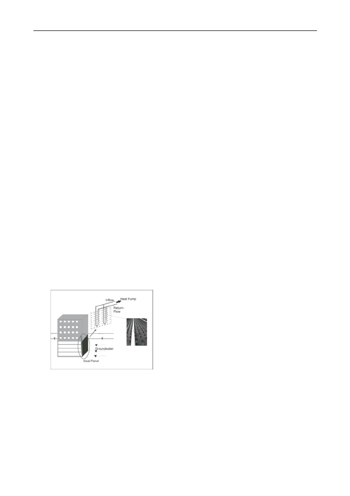
flexible. The principle of the thermo-active seal panels is shown
in Figure 2.
Figure 2. Principle of the thermo-active seal-panel
The main applications for the thermo-active seal panels will
be underground structures with direct contact to groundwater. In
this case a sealing of the structure is necessary anyway. By
thermal activation of the system two functions (sealing and
energetic function) can be combined. So, the additional
installations costs for the geothermal plant are relatively low
comparing to a common BHE.
The efficiency of the thermo-active seal panels was tested in
large scale laboratory tests under different condition. The
determined heat output varied between 30 W/m² and 300 W/m²,
whereby the higher values correspond to high flow rates in the
heat exchanging system. The reason for this is that higher flow
rates lead to a turbulent flow in the pipes and thereby to a better
heat transfer between fluid and pipe. Additional, the thermal
resistance of the system was measured approximately. The
achieved values varied between 0.03 (mK)/W and 0.3 (mK)/W
depending on the boundary and system conditions. According to
the heat output the lowest values (optimum) belong to high flow
rates.
In the laboratory tests different boundary conditions and
system conditions were tested. The results have shown, that the
decisive parameters for the heat output are the heat transmission
area (characterized especially by the pipe distance, the leg
distance between inflow and return flow and the pipe diameter),
the flow rate in the heat exchanging system and the soil
conditions (especially soil type, temperature, groundwater).
More details can be found in Kürten et al. (2012).
4 HEAT TRANSFER BETWEEN GEOTHERMAL
SYSTEM AND SUBSOIL
4.1
Fundamentals
For the planning and design of near surface geothermal plants
the possible heat output of the systems for the existing boundary
conditions has to be known. Empirical values are documented in
the German guideline VDI 4640-2 (2009). These values are
only valid for borehole heat exchangers and small installations
(up to 30kW) as well as homogeneous conditions. For any other
cases numerical simulations are necessary to guaranty a high
efficiency of the system. Direct simulations (finite element
methods, finite difference methods, etc.) are complicated and
computationally very demanding. The reason is that the
necessary scale (in time and space) for the explicit simulation of
the heat exchanger and the simulation of the heat transport in
the soil is different in a large order of magnitude. So, new
methods are needed to reduce simulation time and the
complexity of the model without losing accuracy.
One idea, which often has been used in the last years, is the
transformation of the different processes to thermal resistances.
The different thermal resistances can be superposed to a total
thermal resistance. Then, the heat flow between geothermal
system and soil can be calculated as the product of the total
thermal resistance and the effective temperature difference. For
the overall system the difference between soil and fluid
temperature has to be used.
The difficulty in describing the heat transfer from the soil
and the geothermal systems is therefore coupled to the accurate
formulation of the total resistance of the systems. This value
has to be formulated for each system depending on the relevant
conditions. In the following the approach used for the BHE as
well as the principles of a new model for plane structures
developed by the authors will be shown.
4.2
Heat transfer model for BHE
In common literature many calculation models for the thermal
resistance of a symmetrical system (such as BHEs) are
documented and implemented in several software programs.
Most of them are based on the work of Hellström (1991) as well
as the applied model for determining the decisive parameters for
the heat output from smouldering. A detailed model description
can be found in Mottaghy and Dijkshoorn (2012). In the model
the BHE is assumed as a 1D-Line-Element, which is integrated
in a Finite-Difference-Mesh. The processes inside the BHE are
modelled with the help of thermal resistances. The coupling
with the software program is realized by passing over
temperature boundary condition and heat flow rates. The model
is implemented in the Finite-Difference-Program SHEMAT
(Simulator for heat and mass transfer, see Clauser 2003). The
program can simulate coupled heat and mass transfer (e.g.
groundwater flow) and it has been proven for the simulation of
geothermal systems.
Fundamentally, the thermal resistance for a coaxial probe
depends on the pipe-diameter (inner and outer pipe), the pipe
material, the flow rate, the heat exchanging medium and the


