3425
Technical Committee 307 + 212 /
Comité technique 307 + 212
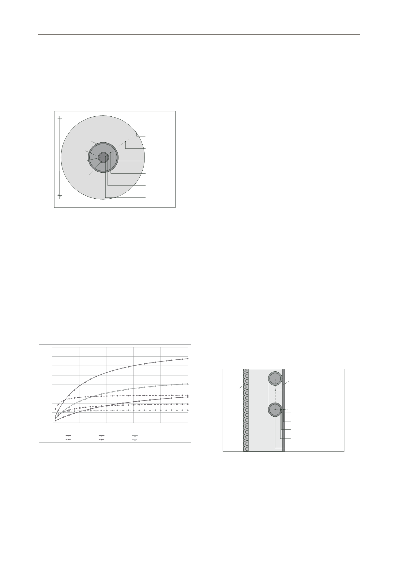
backfill material (s. Figure 3). The main heat transport
mechanisms are conduction (in the backfill material as well as
in the inner and outer pipe) and convection (in the fluid). The
conduction depends mainly on the material properties
(characterized by the thermal conductivity) whereas the
convection depends on the flow rate and the properties of the
fluid (especially viscosity and density).
Backfill
(Sand)
Inflow
Return Flow
276 mm
Convection
(Fluid)
Heat Conduction
(Inner Pipe)
Convection
(Fluid)
Heat Conduction
(Outer Pipe)
Heat Conduction
(Backfill)
Heat Transfer
Dump/Backfill
Dump Material
Outer Pipe
(DN 100)
Inner Pipe
(DN 50)
Figure 3. Heat transfer processes for the coaxial probe installed in the
smouldering dump.
Every existing transport mechanism can be described with
the help of thermal resistances. The different resistances can be
combined with a series connection to a total connection and a
total thermal resistance respectively. Details for the coaxial
probe can be found in Mottaghy and Dijkshoorn (2012).
Post-test calculations of the in situ tests were performed to
calibrate the applied model. After that, several analyses were
carried out to identify the most important parameters for the
geothermal utilization of a smouldering. As an example the
influence of the thermal conductivity of the dump and the
backfill material for each BHE is shown in Figure 4. The
differences between the BHEs are caused by the different
temperature regimes in the heat exchanging fields (see Figure
1). It can be seen that the thermal conductivity of the dump
material is the most important parameter. In contrast, increasing
the thermal conductivity of the backfill material has a less
important influence.
0
100
200
300
400
500
600
700
800
0
1
2
3
4
Heatoutput[kW/m]
ThermalConductivity[W/mK]
5
BHE1 (dumpmaterial)
BHE2 (dumpmaterial)
BHE3 (dumpmaterial)
BHE1 (backfillmaterial)
BHE2 (backfillmaterial)
BHE3 (backfillmaterial)
Figure 4. Influence of the thermal conductivity (dump and backfill
material) for the heat output
The thermal conductivity of the existing dump material was
determined in the laboratory. As a result, a value of 0.4 W/(mK)
can be assumed. As expected the thermal conductivity of the
material is very low. Additional, Thermal Response Tests
(TRT) were carried out for each BHE. The resulting effective
thermal conductivities varied between 1.0 W/(mK) (field 3) and
2.2 W/(mK) (Kürten et al. 2009). The effective thermal
conductivity obtained by the TRTs cannot be equated with the
thermal conductivity as a material property. It is rather a
combination of all thermal processes involved. For the
geothermal utilization of a smouldering the high underground
temperature and the thermal radiation must be taken into
account. For transferring the results to another site, the
determining of the correct effective thermal conductivity will be
the main problem.
In summary, the heat transfer inside the dump (heat
replenishment) is the limiting factor the geothermal utilization
of a smouldering. This is the reason why the achieved heat
output of the pilot plant is relatively low comparing to the high
temperatures inside the dump. Nevertheless, by the presented
research project it could be shown that geothermal utilization of
smouldering mining dumps is possible.
4.3
Heat transfer models for plane structure
For symmetric systems such as a BHE several approaches for
the calculation of the heat transfer between ground and soil with
the help of thermal resistances exist. In contrast, for plane
structures there are no equivalent approaches documented. This
may be due to the fact that the occurring processes are more
complex due to the missing rotation-symmetry.
The developed thermo-active seal panels are characterized
by a plane heat transfer. Nevertheless, in dependency of the
boundary conditions the possible heat output of the systems
must be describes realistically for an effective plant design. For
this, a calculation model, which will be also implemented in the
software program SHEMAT, has been developed by the Chair
of Geotechnical Engineering at RWTH Aachen University.
The basic principle of the new calculation model
corresponds to the existing model for a BHE (see section 4.2).
The processes inside the thermo-active structure will be
summarized to a total thermal resistance. The coupling between
SHEMAT and the calculation model will be realized by passing
over temperature boundary conditions and heat flows.
For the development of the calculation model two main
aspects have to be considered. On the one hand, the heat
transfer isn’t symmetric. The heat transfer from the ground to
the heat exchanging system should be the priority flow. Heat
flows from the room have to be minimized to avoid a thermal
circuit. On the other hand, the inflow and the return flow of the
heat exchanging pipes are spatially separated. This means, that
for a numerical simulation the heat exchanging systems cannot
be design as a 1D-dimensional line-element only but rather as a
2D-dimensional element.
For determining the total thermal resistance for a plane
structure the involved processes must be separated. The decisive
single processes are shown in Figure 5.
Heat Transfer
(Soil - Sealing)
Heat Conduction (Sealing)
Heat Conduction (Pipe)
Heat Transfer
(Pipe - Fluid)
Heat Convection (Fluid)
T
In
T
Out
Heat transfer (fluid)
Soil
Concrete
Room
Sealing
Insulation
Figure 5. Heat transfer for a plane structure - thermal processes involved
The single processes can be transferred to a thermal
resistance model (see Figure 6). It can be seen that there are
three determining heat flows: heat flow due to the temperature
difference between the two sides of the wall and the heat flow
due the temperature difference between heat exchanger and
ground and the room respectively. According to the
superposition principle the two heat flows can be overlapped.
The existing triangle mesh of the thermal resistances can be
simplified to a star-network (see Figure 7).


