2705
Technical Committee 212 /
Comité technique 212
Proceedings of the 18
th
International Conference on Soil Mechanics and Geotechnical Engineering, Paris 2013
At the same time the author was requested to conduct
driveability predictions using wave equation analysis of piles
(WEAP) to assess if the casings could be used as driven piles.
One of the main criteria of interest was whether the piles could
be driven far enough into the soft rock to achieve the required
tension resistance, which was a controlling aspect of the tripod
foundation design. This appeared to be the case, and with a
smaller hammer than was being used for the dynamic testing.
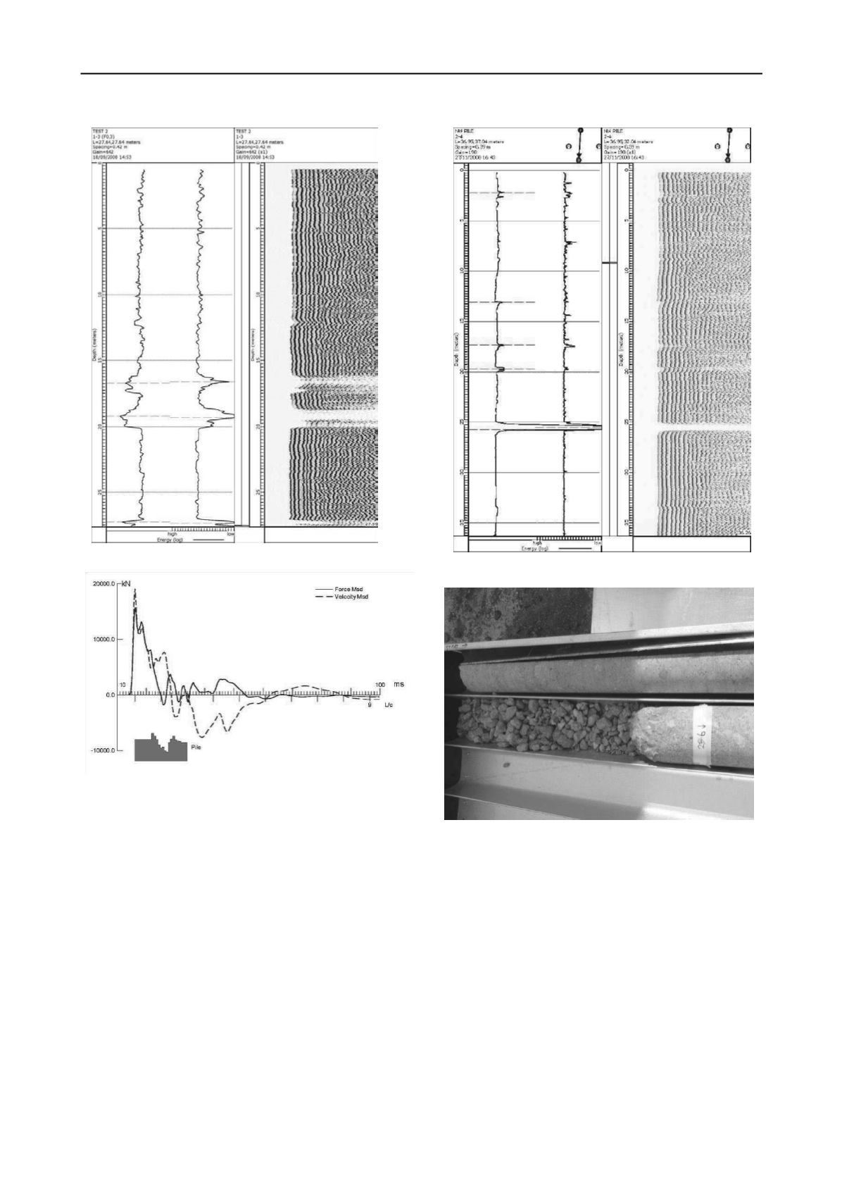
Construction started on the East Abutment and, again,
problems with the concrete quickly became obvious. CSL
testing indicated a significant defect at 25m below the top.
(Figure 6). Drill cores were conducted to investigate and repair
the problem zone. Coring confirmed a zone of aggregate only
with no cement - exactly as predicted by the CSL. (Figure 7).
Further attempts were made to improve the concrete but in
every case problems were detected. If anything the concrete
problems got worse, both in size and significance. (Figure 8).
Prior to the abandonment of socketed piles one further test
was conducted on the last socketed abutment pile. No access
tubes had been cast in this pile so low strain axial sonic pile
integrity testing using a Pile Integrity Tester
®
(PIT) was
conducted (Figure 9). No integrity problems were detected
using this method. A very slight increase in velocity was
detected at the top of the socket but this was attributed to the
change in diameter from 900mm to 780mm.
6 DRIVEN TEST PILE
Soon after the WEAP analyses were conducted a third test pile
was installed. Again, this was positioned adjacent to the bridge
location and was not to be incorporated into the contract works.
The 900x20mm steel tube casing was modified by removing the
bottom collar and installing a 900x50mm driving shoe of 0.8m
length. This third test pile was driven with a Junttan HHK9A
hammer, which has a 9t ram. The pile was driven through the
gravels and cobbles and 12m into the soft rock at a final set of
2.9mm/bl. A restrike test was conducted the next day using the
Junttan HHK16A hammer, which has a 16t ram. The pile had
"set-up" to such an extent the set had reduced to 1.3mm/bl
despite the hammer being significantly larger than the hammer
used to drive the pile. The resistance demonstrated during the
Figure 5 - PDA measurements Test Pile 2
Figure 4 - CSL test results Test Pile 2
Figure 7 - Core of East Abutment NW pile
Figure 6 CSL test result East Abutment NW pile


