2704
Proceedings of the 18
th
International Conference on Soil Mechanics and Geotechnical Engineering, Paris 2013
Proceedings of the 18
th
International Conference on Soil Mechanics and Geotechnical Engineering, Paris 2013
The piles were 900mm OD with 20mm wall thickness steel
tubes with a concrete socket in the rock. At this site the socket
was 780mm diameter. The concrete was to be continued into
the pile a sufficient distance to transfer the load by
steel/concrete bond - about 8m. The concrete was to be heavily
reinforced owing to high tension loading, with ten clusters of
three 36mm diameter bars.
The contractor initially installed the casings with a large
down-the-hole hammer. This used a 940mm hammer
positioned at the bottom of the excavation and powered by
compressed air. The hammer drags the casing behind it by
engaging a collar at the bottom of the casing. Upon reaching
rock the hammer can disengage the casing and bore a socket.
At this site the hammer was removed after reaching the rock
and a 780mm rock-roller drill was used to drill the socket. The
method was well known to the contractor and is reputed to have
excellent production rates in hard ground. However, at this site
the gravels and cobbles were loose and saturated. There was
frequently insufficient resistance to start the hammer and it
stalled frequently.
Progress was slow and delays were
extensive.
Owing to the remote site concrete was produced by a mobile
batch plant at the site but was otherwise unremarkable. The
piles were concreted using a tremie pipe with the shaft full of
water or drilling fluid.
4
SOCKETED TEST PILES
The first pile constructed at the site was a test pile that was not
to be incorporated into the bridge. It was a vertical full sized
pile. To provide for dynamic testing the socket concrete was
extended to the top of the pile. The test gauges were initially
attached to the concrete through "windows" in the steel tube and
the pile was considered as a combined section. The top of the
steel tube was cut back 25mm below the top of concrete to
ensure the hammer acted on the concrete. A 19mm plywood
cushion was used between the hammer and the pile.
Other than the permanent casing there was nothing
unusual about the dynamic testing. Concreting had been
completed about 14days prior to the test.
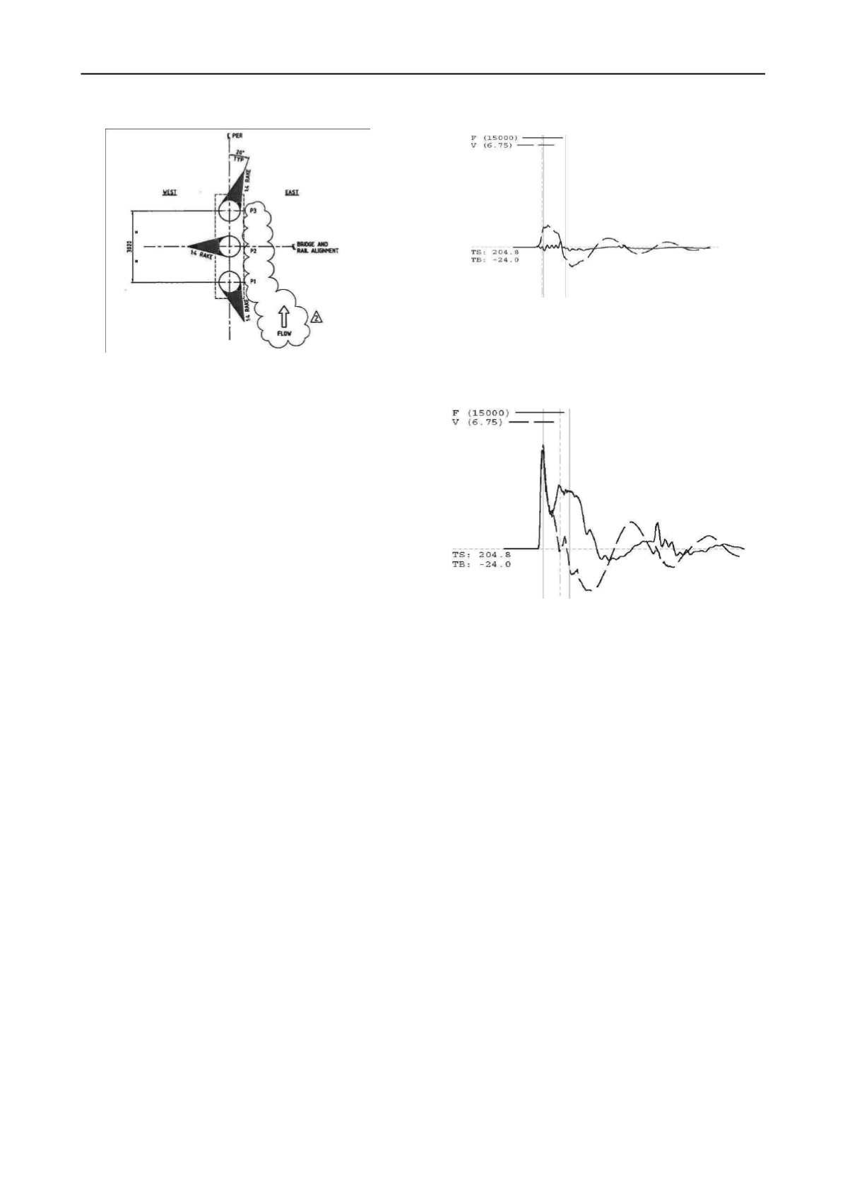
Very strange measurements were obtained initially, with
almost no force measured in the concrete. (Figure 2). In
addition it was observed after several blows that the concrete in
the "window" had moved down relative to the steel.
The gauges were moved to the steel tube and again very
strange measurements were obtained The only way the
measurements made sense was to use the properties of the steel
tube only and assume the concrete was not working as part of
the pile. (Figure 3). The hammer was removed and it was
noted the top was level with the steel. The hammer was indeed
acting on the steel tube.
The concrete between the pile top and the gauges must
have crushed by up to 44mm, being the 25mm upstand of
concrete plus the thickness of the pile cushion. The hammer
was replaced, with increased cushion, and more blows were
applied with no improvement of the measurements and with
further crushing of the concrete.
A second test pile was constructed and this time access
tubes for CSL testing were cast in the pile. Concreting records
showed potential problems near the toe and part way though the
pour. Observations suggested the concrete had started to set
early, possibly due to the extreme temperatures. CSL test
results confirmed problems at the toe and between 15-20m
below the pile top. (Figure 4).
Dynamic pile testing was also conducted and confirmed
concrete problems. Gauges were attached to the concrete
through windows in the steel casing. Results suggested there
was a significant defect 15-20m down the shaft. The steel was
also not contributing to the pile. Transfer of load by steel to
concrete bond seemed unreliable. (Figure 5).
5
PRODUCTION SOCKETED PILES
As it was thought the cause of the concrete problems was
known, and related to temperature and the behaviour of concrete
additives, it was decided to proceed with production piles, but
only at abutments, where repairs such as additional piles were
possible.
Figure 3 PDA measurements on steel
Figure 1 - Pier foundation Layout
Figure 2 - PDA measurements on concrete


