3123
Technical Committee 301 /
Comité technique 301
Driven concrete 30x30 cm 4-12 m long piles are applied.
The length of piles depends on the depth of the bearing gravel
and pebble layer, in which the pile tips are at least 0.5 m deep.
Due to variations of geological conditions within the
construction site two types of footings were used in the project
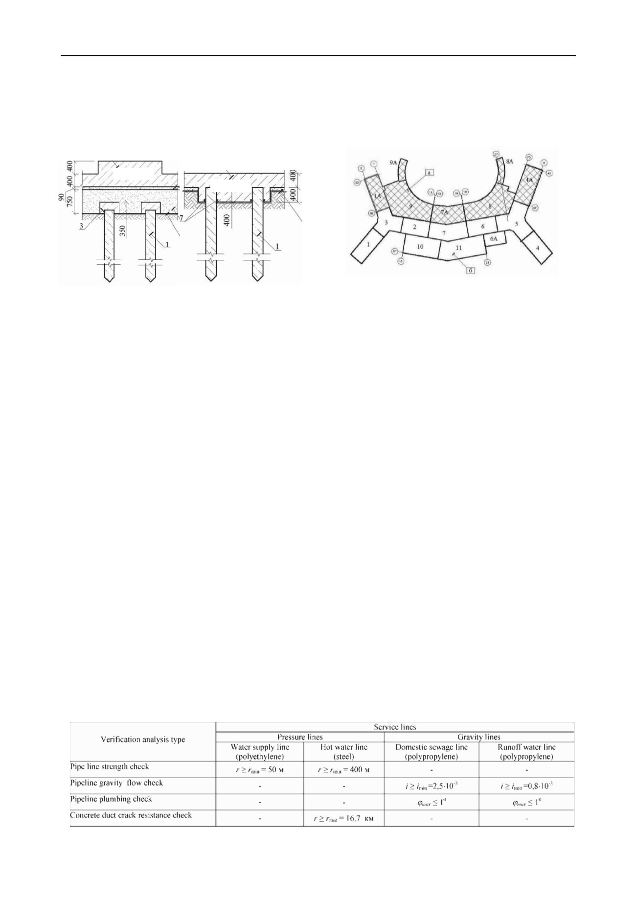
design (fig. 10)
Figure 10. Foundation types for plot 17.
Type 1 (Fig. 10, left) is a concrete raft 400 mm thick with
greater, up to 800 mm thickness, under bearing structures with
flat bottom on pile foundation with intermediate sand and
gravel layer. Presence of this layer practically excludes lateral
seismic load transfer. The intermediate 0.75 m thick layer,
consisting of local sand and sand-gravel soils, compacted layer
by layer, is a damper, it is filled over pile heads having
concrete caps. A layer of geotextile is placed between piles and
under their caps separated from piles by shockproof polystyrol
layer.
Type 2 (Fig. 10, right) is applied for the buildings, sitting on
soil base, containing peats and peaty soils, having Young
modulus of 5…6 МPа. Here a solid raft is designed of variable
thickness, leveled on top, with pile heads fixed in the raft. The
piles, bearing lateral seismic loads, have strong reinforcement in
accordance with construction codes.
The pile field is designed to withstand the main and the
special (seismic) combination of loads.. The design load,
applied to the piles, is 750 kN for the main combination and
1000 kN for the special one. The piles bearing capacity of 1000
kN was proved by static load tests. The design lateral load on
the piles does not exceed 35 kN for pile-raft rigid fixation.
Hotel, apartments and support services at plot D1 are located
in the single building, separated by settlement and anti-seismic
joints into sections (Fig. 11). Overall dimensions of the building
are 150x264m.
Soil conditions of the plot D1 vary significantly within the
building footprint, which determined the choice of different
types of foundations within the same building.
On the part of the site (blocks 1-7, 10, 11 on figure 11),
located close to the shore, surface part of the geologic section
consists of large thick deposits of sand and gravel, underlain by
gravel-pebble soils. For these conditions, the foundation is
designed as a cast reinforced concrete raft with thickness of 400
mm. Under heavily loaded walls and columns 800 mm thick
upward ribs are provided to increase stiffness of raft.
A further from the shore (Blocks 1A, 4A, 7A, 8, 8A and 9 in
Figure 11) upper part of geological section consist of weak
man-made soil, covered by fill produced during engineering
preparation of the construction site. Due to low strength of these
soils, they can not be used as the foundation base. Therefore, to
minimize the differential settlements of adjoining blocks, pile
foundation with intermediate cohesionless soil cushion were
designed similar to the one designed at plot 17 (Fig. 10 left).
F
igure 11. Foundation layout for building on site D1. Hatched areas
represent pile foundation, blank areas – raft foundation.
5
GEOTECHNICAL FEATURES OF UNDERGROUND
PIPELINES DESIGN.
In order to ensure operation of the main Olympic facilities
on Imeretin lowland terrain it was necessary to build a multi-
kilometer long and dense network of various underground
service lines for various purposes (heat and water lines, sewage
and rainwater systems), of various liquid transportation
principles (non-pressurized and pressurized), made of various
pipeline materials (steel, polyethelyne, polypropelene), of
various pipe diameters (250…1580 mm), with and without
protection.
The main issue in foundation design for service lines is the
account of potential considerable differential settlements of soft
consolidating soils and, as a consequence, those of pipelines,
caused by fill loading of the terrain. According calculation
results the settlements of 5…20 m thick soft soils could be up to
0.7 m and could develop for several months or years even if
special geotechnical techniques are applied to accelerate soil
consolidation (sand and geosynthetic drains, temporary loading
fill, jet stabilization, etc.). Application of other techniques of
soil stabilization (stone columns, soil reinforcement, jet
stabilization, etc.) was neither possible for financial and tight
schedule reasons.
In view of the project of such scale the NIIOSP specialists
had to develop special recommendations for service lines that
outlined admissible deformations, missing in Russian
construction codes (see Table 2). The assumed approach was
based on limit state design analyses. This enabled selection of
effective foundations types for the whole spectrum of numerous
waterlines. Thereafter (Fig. 13) some service lines were
designed to sit on driven concrete piles, other ones on cast
concrete strip footing on natural or on improved ground, made
by complete or partial replacement of soft laguna deposits by
Type 1
Type 2
Table 2. Ultimate admissable deformations of service lines.
Note.
r
and
r
min
are design and minimally admissible radius of pipeline curvature;
i
and
i
min
are design and minimally admissible pipeline
slopes;
φ
and
φ
max
are design and maximally allowable angle of rotation in pipeline joints.


