3121
Technical Committee 301 /
Comité technique 301
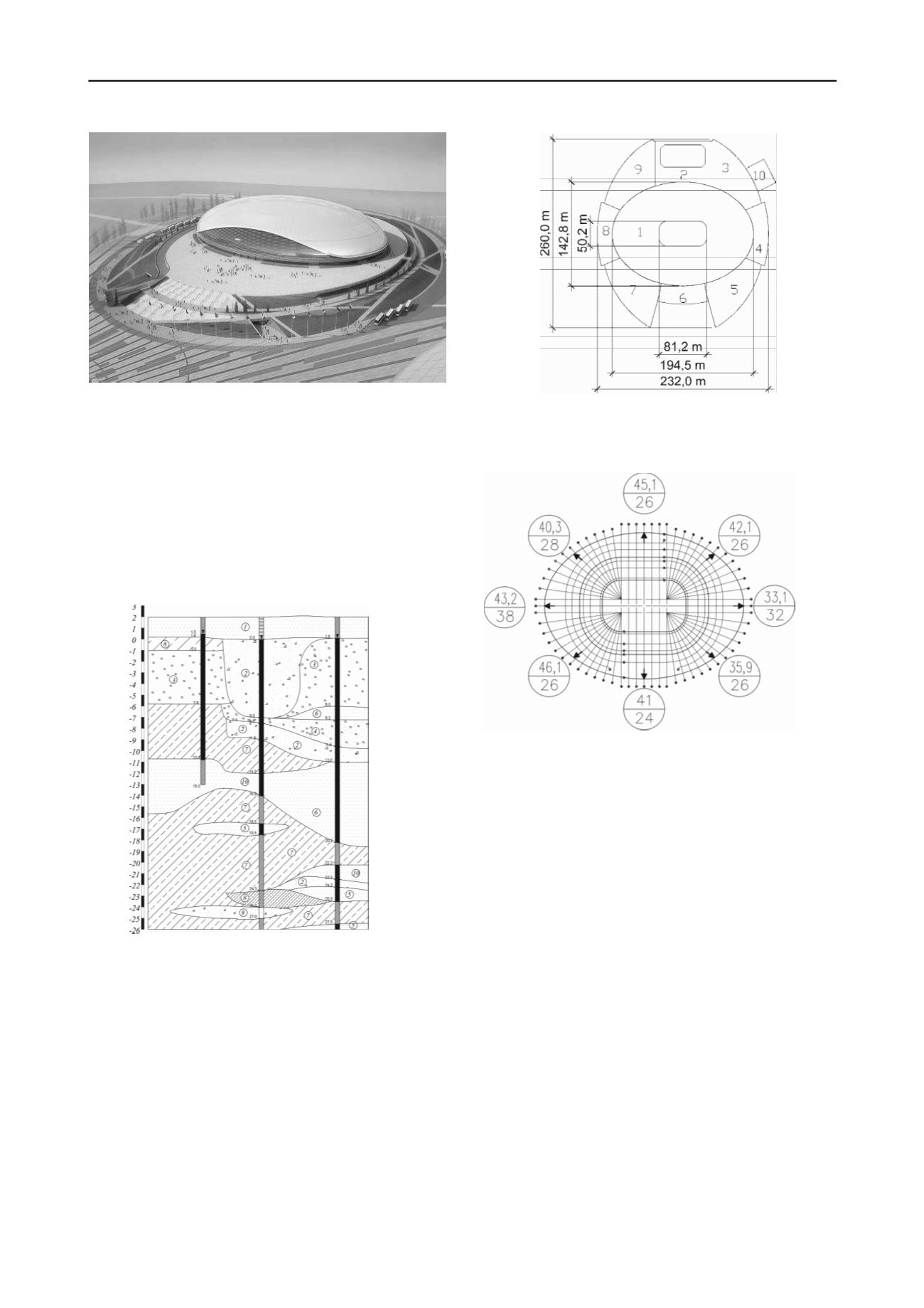
Fig. 3. Overview of Big Ice Arena.
Raft analysis was performed with the account of joint
footing-superstructure analysis for the service and ultimate limit
states. ULS analysis included the main and characteristic
combinations of design loads with seismic action in both
directions along the structure main axes. For characteristic
combination the analysis included the raft shear along its
bottom while for stylobate structures the exess of the vertical
component of the design eccentric load over vertical force of
limit state force in the case of one-sided soil upthrust, caused by
seismic action. Shear verification was done for horizontal force,
defined as a geometrical sum of horizontal loads in
characteristic combination along the principle axes.
Fig. 4. Arena geological profile: 1. Coarse grained sand; 2. Gravelly
soil; 3. Pebble soil with sand fill; 4. Gravely sand 5. Fine to medium
sand, with thin seams of sandy clay; 6. Sand; 7. Plastic sandy loam; 8.
Sandy loam with pebbles; 9. Gravel and pebble mixture; 10. Fine sand.
The values of loads, applied to the footing rafts, were
determined with the account of safety factor К = 1,2 for
important structures. Soil stiffness parameters were reduced as
per К = 0,9. Soil base values were calculated as per the
geological columns data within the structure footprint the soil
base was simulated by linearly deforming layer. The 3D rafts
analysis was done with the help of finite elements technique.
The results enabled determination of cross section
configuration of the rafts, internal forces in them and the
required reiforcement.
During BIA construction period settlements of the main
arena raft were measured. The measured settlements by the end
of construction period were close to those predicted (Fig.6).
Fig. 5. Layout of Rafts of Big Ice Arena. 1. Raft of Main Arena; 2. Raft
of workout arena; 3... 9 Rafts of service premises and bypass road; 10.
Raft of refrigeration center.
Figure 6. Mean value (mm) of measured (numerator) and analytical
(denominator) settlements of arena raft footing.
3
OFFICE BUILDING OF ORGANIZING COMMITTEE
Office building of Organizing Committee of Olympic
Games is located at 1200 m distance from the main facilities.
The building consists of 9-storey main part and 3-storey parts,
surrounding it (Fig. 7). A one-level parking lot is designed
under the whole building is similar to a trifolium (one leave
width is 18,7 m). The high-rise part of the building is divided
into counter-seismic blocks, sitting on the solid raft. The
structural design of the building consists of a framework with
stiffness diaphragms in each antiseismic block. The main
bearing structural elements of the building are made of cast
concrete. The construction site dimensions are 120х90 m.
High-rise and low-rise sectors are divided by compensation
joints. Mean design distributed load on the soil base from the 9-
story component is 200 kPа, that from the 3-story is100 kPа.
The office building of the Organizing Committee of Olympic
Games is located on the site that is certainly the most
unfavorable as to its geotechnical conditions. Top ≈4,5 m layer
composed of relatively strong clays. Underneath the top layer
soft and liquid plastic clays of very low strength are lying up to
21 m depth. Some boreholes showed peat pockets at 9 to 17 m
depth. At 21…23 m depth there occur coarse sands, below 23 m
depth gravel-pebble muxture. Clay soils on the site feature
organic content up to 10…15%.


