2677
Technical Committee 212 /
Comité technique 212
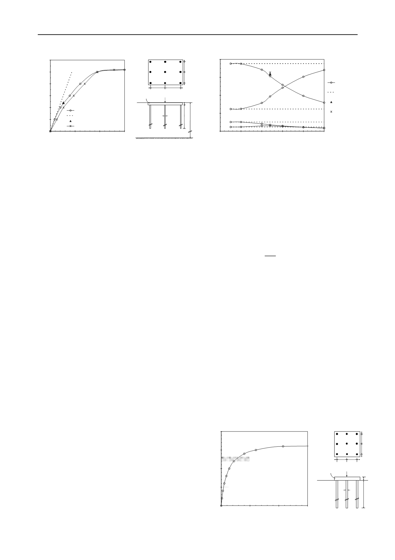
Figure 3. Load-settlement response and piled raft analysed
873 kN in compression and 786 kN in tension. The figure also
shows a fair agreement with the load-settlement curve obtained
by Poulos for a flexible raft (i.e.
t
r
= 0.5m giving
K
rs
= 0.8), as
previously reported. It is noted that, as the load capacity of the
piles becomes nearly fully utilized at a load of about
P
= 10-12
MN, the load-settlement behaviour reflects that of the raft,
which is significantly less stiff than the overall pile-raft system,
while the load carried by the raft starts to increase significantly
(Fig. 4). As previously observed, the fact that some of the piles
(usually the stiffer piles located around the perimeter of the
group) are close to their ultimate capacity is not an issue for a
piled raft and is actually inevitable for an efficient design.
The load sharing between the raft and the piles as a function
of the total applied load reported in Fig. 4 shows a significant
reduction of the total load carried by the piles with increasing
load level. Under a total load
P
= 12 MN, the figure shows a
good agreement with the load carried by the piles predicted by
Poulos for the rigid raft and a slightly less agreement with that
obtained for the flexible raft. Overall, the comparison shown in
Figs. 3-4 demonstrates the importance of considering non-linear
behaviour of the pile-raft system in order to obtain realistic
predictions of the settlement and the load sharing between the
raft and the piles. Assumption of linear elastic behaviour
beyond a load of about 10 MN would lead to an under-
estimation of the settlement and an over-estimation of the
amount of load carried by the piles, with a consequent over-
design of the requirements for structural strength of the piles.
As emphasized by Poulos (2001), an analysis which accounts
for soil non-linearity, even though in an approximate manner, is
preferable to a complex analysis in which linear behaviour is
assumed.
3.3
Design example
The hypothetical design example shown in Fig. 5 is described in
order to demonstrate that, in suitable ground conditions, a
significant reduction of the piling requirements can be achieved
with the use of a piled raft as compared to a conventional pile
foundation. Two foundation systems are evaluated:
(1) A 4x4 pile group (i.e. with no raft contribution) designed
according to a traditional approach in which an overall
(geotechnical) factor of safety
FS
= 2 is assumed to apply
to the maximum axial force of the single pile;
(2) A piled raft (3x3 group) in which
FS
= 2 is assumed to
apply to the total force acting on the whole pile-raft
system.
A total force
E
k
= 25 MN is acting on the foundation and a
maximum allowable settlement of 25mm has been prescribed.
The analyses have been carried out using PGROUPN (non-
linear soil model) with the parameters indicated in Fig. 5 (the
raft may be considered as fully rigid being
K
rs
= 10.5). The
initial solution of an unpiled raft (11m x 11m) has been
discarded due to both bearing capacity and settlement
requirements, given that the raft bearing capacity is equal to
54.5 MN (based on
q
u
= 6
C
u
) and the raft settlement results in
Figure 4. Load sharing between raft and piles
38mm. Thus, a pile-group solution is considered and is found
that a group of 4x4 piles (30.5m long) at a spacing of 3
D
= 3m
is required in order to achieve
FS
= 2 on the maximum axial
force (
V
max
) of the corner pile, (i.e.
Q
all
= 2421 kN >
V
max
= 2390
kN). It is noted that the calculated pile-group settlement is equal
to 14mm, i.e. below the allowable value of 25mm, thereby
indicating that a design optimization may be achieved.
A piled raft solution (3x3 group with pile spacing of 4
D
=
4m and pile length of 20m) is then evaluated following the
methodology outlined in the International CPRF Guideline
(Katzenbach 2012). According to the guideline, a sufficient
safety against failure of the overall pile-raft system is achieved
by fulfilling the following inequation:
≤
→
∙
≤
,
→
∙
∙
≤
,
(2)
where
E
k
is the characteristic total force acting on the CPRF,
γ
F
and
γ
R
are the partial safety factors on actions and resistance,
respectively, and the characteristic value of the total resistance
R
tot,k
has to be derived from the load-settlement response of the
CPRF and is equal to the load at which the increase of the
settlement becomes increasingly superproportional, as
determined from a "numerical" load test. In order to allow a
direct comparison with the above pile-group solution, it is
assumed that an overall
FS
= 2 applies to the force
E
k
(this
assumption is equivalent to consider a value of
γ
F
·
γ
R
= 2). This
implies that Equ. (2) is fulfilled by proving that
R
tot,k
≥
2
E
k
=
2·25 = 50 MN. Thus, using PGROUPN, a numerical load test
has been performed to generate the typical relationship between
the settlement and the total load (i.e. the CPRF overall
resistance), as illustrated in Fig. 5. From this figure, it can be
seen that, up to the loading of 50 MN, the increase of the
settlement is not yet superproportional (i.e.
R
tot,k
> 50 MN),
implying that no significant failure of the CPRF has occurred.
Thus, the ultimate bearing capacity (ULS) of the piled raft has
been proved. It is noted that the maximum pile axial load is
equal to
V
max
= 2210 kN, which would give
FS
= 1.5 (being the
pile capacity
Q
ult
= 3358 kN); however, in contrast to
conventional pile foundations, the proof of the bearing capacity
Figure 5. Load-settlement response and piled raft analysed
0
5
10
15
20
25
30
0
50
100
150
Central settlement (mm)
Total applied load (MN)
PGROUPN - Non-linear
PGROUPN - Linear elastic
Poulos (2001) - Non-linear (rigid raft)
Poulos (2001) - Non-linear (flexible raft)
1m 4m
4m 1m
1m
2m
2m
1m
20m
10m
1m
E
p
= E
r
= 30 GPa
ν
p
=
ν
r
= 0.2
E
s
= 20 MPa
ν
s
= 0.3
P= 12 MN
0.5m
0
20
40
60
80
0
5
10
15
20
25
Total applied load (MN)
Load carried by raft/piles (%)
PGROUPN - Non-linear
PGROUPN - Linear elastic
Poulos (2001) - Non-linear
(rigid raft)
Poulos (2001) - Non-linear
(flexible raft)
Raft
Corner pile
Centre pile
Piles (total)
0
25
50
75
100
0
250
500
750
Settlement (mm)
Overall resistance (MN)
R
tot,k
E
k
1.5 4m 4m 1.5m
1.5m
4m
4m
1.5m
20m
2m
E
p
= E
r
= 30 GPa
ν
p
=
ν
r
= 0.2
E
s
= 75 MPa
ν
s
= 0.5
C
u
= 75 kPa
α
= 0.6
Hyperbolic factors:
R
f shaft
= 0.50
R
f base
= 0.99
R
f raft
= 0.90
E
k
= 25 MN
D=1m


