2668
Proceedings of the 18
th
International Conference on Soil Mechanics and Geotechnical Engineering, Paris 2013
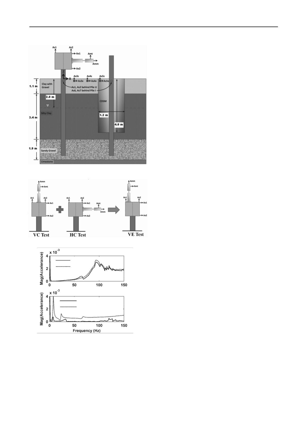
Figure 2. Inertial shaker configurations for the three test types.
Figure 3. Comparison of VE test to combination of VC and HC tests
for swept sine loading on pile I in improved soil. Top: VC response
from VC and VE tests; Bottom: HC response from HC and VE tests.
For each combination of pile type (U or I), excitation type
(C, R, or S) and intensity (1, 2, or 3), three separate tests were
performed with the shaker mounted in the vertical-centric (VC),
horizontal-central (HC), and vertically eccentric (VE) positions,
shown schematically in Figure 2. The VC test primarily
activates the vertical mode of vibration, while the HC test
excites the coupled horizontal-rocking mode. These two tests
have traditionally been performed independently, creating
uncertainty as to the similarity of contact and soil conditions in
the two separate tests. The VE tests were studied as a method to
reduce such uncertainties and improve efficiency by activating
the vertical and coupled horizontal-rocking modes
simultaneously.
A total of 109 full-scale vibration tests were performed on
the piles using the three excitation types and three shaker
configurations described above, with a range of loading levels
and excitation bandwidths. Typical experimental results are
shown in Figure 3 for pile I. The results demonstrate that a
single VE test can be used to characterize the vertical and
horizontal-rocking modes normally obtained from separate VC
and HC tests. Due to the difference in shaker orientation and
location in the VE and HC tests, the HC response to HC
excitation (HC/HC) differs from the HC response to VE loading
(HC/VE). However, such differences are accounted for in the
equations of motion of the shaker, pile cap, and un-embedded
pile stem, and the HC and VE responses can be evaluated
against their theoretical counterparts for both test types using a
common set of soil-level impedance functions. A more detailed
description of the test set up and experimental results can found
in the Experimental Setup Report archived together with the
data from all experiments described herein on the NEEShub at
To refer to the various tests, a naming convention of (Pile
Type)-(Test Type)-(Excitation Type and Level) will be used.
For example, U-HC-R3 refers to a test performed on pile U in
unimproved soil with the shaker in the HC configuration, with
random (R) excitation at the highest intensity level (3). In the
naming convention, test types VC and HC can replace VE, and
excitation types S (swept-sine) and C (chaotic impulse) can
replace R. For any accelerometer, the accelerance is defined at
each frequency as the ratio of the directional acceleration to the
force applied by the moving mass of the shaker. Accelerance is
used as the main frequency response function for comparing
and analyzing experimental and analytical results. For example,
VC/VE refers to the vertical-centric acceleration due to vertical-
eccentric forcing. The pile-cap and stationary portion of the
shaker are assumed to undergo rigid-body motion, and a set of
vertical, horizontal and rotational accelerances at the centroid
can therefore be easily calculated using acceleration
measurements from three non-collinear points on the pile-cap.
2 THEORETICAL MODEL
The theoretical accelerance of the system is calculated using
frequency-domain rigid-body equations of motion for the pile-
cap and shaker, an Euler-Bernoulli beam-column formulation
for the above-ground pile segment, and the aforementioned 2D
approximate or 3D BEM formulations for impedance functions
at the soil level to account for the dynamic pile-soil interaction
(the BEM models are not discussed in this paper). The soil-pile
impedance matrix relates the force and displacement of the pile
cross-section at the soil surface elevation. Each component of
the impedance matrix is frequency dependent and complex-
valued, with the real part representing the dynamic stiffness of
the pile-soil system and the imaginary part accounting for the
material and geometric damping.
The 2D approximate pile-soil interaction model introduced
by Novak and Aboul-Ella (1978) was used to calculate the soil
impedances with account of the variation of soil parameters
with depth. This model derives the soil reactions from a plane
strain assumption and also incorporates the reaction of the soil
at the pile tip. Upon constructing the stiffness matrices using the
approach, the pile head impedances can be found by solving the
global matrix equations for prescribed unit displacements and
rotations of a pile section at the soil-surface. The model is
limited to hysteretic damping behavior for the soil and a circular
cross section for the pile. Circular sections with equivalent axial
or bending stiffness as appropriate were therefore used to model
the H-piles in this study. Additionally, the model requires that
soil and pile properties are constant for each pile element.
The approach is fast compared to other numerical
alternatives such as the finite element and boundary element
Figure 1. Soil profile, test set-up and sensor arrangement. Pile cap and
shaker shown on pile U in native unimproved soil.
VC/VE
VC/VC
HC/VE
HC/HC


