2660
Proceedings of the 18
th
International Conference on Soil Mechanics and Geotechnical Engineering, Paris 2013
permeability tests as well as a pumping test. The SI also
comprised a set of geophysical investigations. Undisturbed
samples collected from the cohesive layers were subject to
oedometer tests and triaxial tests.
Within the granular deposit, three interbedded layers of clayey
silts with a PI of 10-30% are found at +79m asl (layer D), +59m
asl (layer F) and +45m asl (layer H) with a thickness of 3m, 4m
and 2m respectively (Figure 3).
The cohesionless layers typically have a relative density of 45-
65% and
′
cv
=36°. The soil stiffness profile at small strains was
derived from V
S
measured in situ; a good agreement with the
empirical correlation to N
SPT
values proposed by Stroud (1988)
was found for the granular materials. For the cohesive layers,
the secant stiffness was estimated from c
u
and OCR according
to Koutsoftas and Fisher 1980.
The two level basement requires a 16m deep excavation, so the
raft formation level is at +108m asl. Extensive aquifer
exploitation lowered the groundwater table from +120m asl to a
minimum level of +100m asl in the mid 70’s. With the
relocation of industrial sites outside the urban area the
groundwater table has risen to the current level of +106.5m asl,
resulting in a lightly overconsolidated deposit, with OCR values
ranging between 1.35 and 1.20 in the cohesive layers D to H.
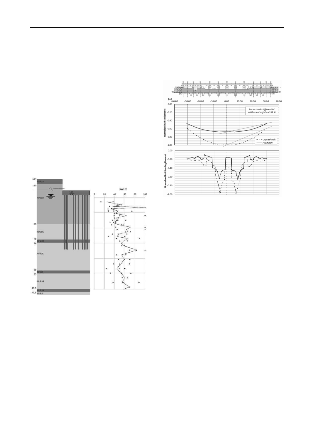
Figure 3 Stratigraphy and SPT tests profile (levels in metres asl)
4 FOUNDATION DESIGN
The Italian Construction Code (2008) covers mixed foundations
and determines that where the raft alone is capable of satisfying
the ULS, the piles can act as settlement reducers and their
design should ensure the satisfaction of the SLS. This implies
that the piles need to be checked for the structural limit states
only.
The main design challenges consisted in accounting for the
presence of deep cohesive layers and achieving a cost-effective
solution. The absence of published data on the behaviour of
existing high-rise buildings founded on mixed foundations in
Milan is noted.
The structural and geotechnical design was developed in phases,
with simplified methods being used for preliminary design
(Poulos 2001; Mandolini
et al.
2005).
From early design stages it was found that an unpiled raft could
carry the load shed from the superstructure alone. The
corresponding stresses, however, require a very thick and
heavily reinforced raft which is not the most cost-effective or
buildable foundation solution. Similarly, there was no feasible
configuration for a fully piled solution, considering the pile
length constraints explained below. The behaviour of an unpiled
raft foundation solution was analysed to guide the selection of
the settlement reducing pile locations and control the raft
stresses and differential settlements (Figure 4).
Figure 4. Unpiled Raft vs Piled Raft: Settlement and Bending Moment
diagrams normalized to the unpiled raft maximum values.
Creep settlements of the cohesionless layers where estimated
according to Burland & Burbidge 1985 for a design life of 100
years.
Due to permeability of cohesive layers ranging between 10
-8
m/s
(layers D and H) and 10
-9
m/s (layer F) and their limited
thickness it was evaluated that primary consolidation should
take place during construction (assumed > 2 years). The
secondary consolidation coefficient was estimated from
ad hoc
oedometer tests subject to a longer than standard duration (6
days ≈ one additional log-cycle) at the relevant design effective
stress. The aim of limiting the impact of creep associated to the
cohesive layers, led to positioning the pile base just below the
cohesive layer D. This corresponds to a pile length to radius of
equivalent circular foundation area ratio of 1.4 which, together
with the pile group-raft area ratio, is identified as the most
effective elements of the system geometry for the minimisation
of the normalised differential settlements (Reul & Randolph
2004).
During the first phases of design the single pile axial resistance
and load-settlement curve were estimated using the K
s
·tan
approach and the method proposed by Fleming 1992,
respectively. The final design stage benefited from the
availability of site-specific preliminary pile load tests which
showed an average unit shaft resistance ranging between 90 and
120kPa and provided load-settlement curves for the calibration
of the FE models. The piled-raft was analysed with the FEM
software Oasys GSA 2010 which links the superstructure,
foundation and ground into a single soil-structure model. The
raft was modelled with 2D shell elements in contact with beam
elements (piles) and a linear elastic soil mass within which
displacements are calculated according to the Mindlin method.
Each pile node has an associated pile-soil interaction coefficient
curve which enables a non-linear response of the pile under
vertical loading. The soil stiffness was developed considering
the part of the load occurring in re-loading conditions and that
in virgin compression as well as the estimated average soil shear


