2661
Technical Committee 212 /
Comité technique 212
strain (
=0.1%) derived from the stiffness degradation curves
proposed by Seed & Idriss 1970 for cohesionless soils.
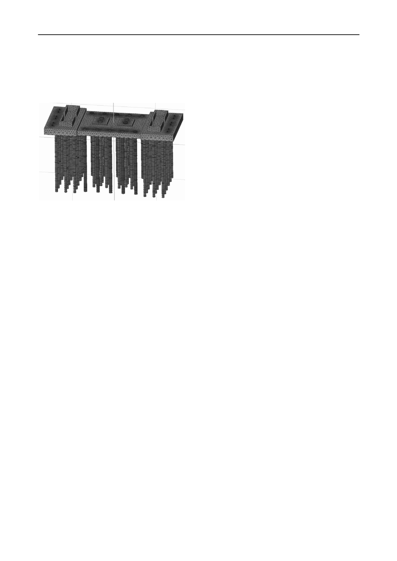
The GSA model was compared with a full 3D FE analysis
developed with MIDAS GTS (Figure 5) which provided similar
settlements, pile axial loads and raft stresses.
Simplified methods are used during the initial optioneering
phase to develop a solution which can then be analysed with
more rigorous tools.
GSA is a reliable and efficient tool for the final design stages
which has shown to match the results of a parallel full 3D FE
piled raft model.
Pile length to equivalent circular raft radius ratio and pile group-
raft area ratio are important elements to consider during design.
A FoS<2 on piles results in higher working load in piles than
would otherwise be the case; this requires additional
consideration for their structural design.
Internal actions on the upper part of the piles are reduced by
avoiding a structural connection between piles and raft without
significantly affecting the raft behaviour. Limiting the
mobilisation of the piles’ shaft resistance minimises the
sensitivity of the raft behaviour with respect to workmanship
problems and local variations of soil conditions.
Assessment of the total settlements requires consideration of
time-dependant phenomena.
Piled rafts can offer a cost-effective foundation solution for
high-rise buildings.
Figure 5. MIDAS GTS 3D FE model of the piled raft.
Creep effects of the concrete in the raft and piles were taken
into account as these affect the long term behaviour of the
foundation. A reduction factor of the young modulus of 1+φ
∞
was adopted with φ
∞
=0.90 for the raft and 0.76 for the piles. In
order to limit bending moments in the top of the piles due to raft
deflection, no structural connection between the raft and the pile
head was provided.
6 ACKNOWLEDGEMENTS
The authors would like to thank Duncan Nicholson, Alessandro
Baliva, and Matteo Minno for their contribution as well as
Marco Beccati for his support from the client’s side.
The piled raft behaviour under horizontal loads was analysed
with PIGLET (Randolph 2006) and the Oasys software ALP
and PDISP.
7 REFERENCES
Burland and Burbidge 1985. Settlement of foundations on sand and
gravel. Proc. ICE, part 1.
The effect of wind induced cyclic actions was estimated
according to the methods described by O’Riordan 1991
(settlements) and Poulos & Davids 2005 (pile stiffness
degradation).
Burland J., Chapman T., Skinner H. D. and Brown M. 2012. Manual of
Geotechnical Engineering, Institution of Civil Engineers.
Half of the maximum raft settlements were estimated to occur
during construction, 33% were associated to creep, 13% to
cyclic loading and 4% to planned nearby buildings. The
potential for tilting due to variations in thickness of the cohesive
layers was estimated to be negligible.
Decreto Ministeriale 14.1.2008 del Ministero delle Infrastrutture.
“Nuove norme tecniche per le costruzioni”. S.O. n. 30 alla G.U. del
4.2.2008, n. 29.
Fleming G.W.K. 1992. A new method for single pile settlement
prediction and Analysis, Geotechnique 42, No. 3 pp 411-425
Koutsoftas, D., Fisher, J. 1980. Dynamic properties of two marine clays,
ASCE J. Geotech Division 106 (GT6), pp. 145-157.
The load percentage split between the raft and the piles
estimated from the FE analyses is 35/65: this matches well with
that proposed by Mandolini
et al.
2005 for (s/d)/(A
g
/A)=4.75.
Mandolini A. 2003. Design of piled raft foundations: Practice and
Development, Design of foundations on bored and auger piles, Van
Impe ed., Rotterdam.
The 1.2m diameter piles have a factor of safety (FoS) ranging
between 1.45 and 1.65, and the 1.5m diameter piles between
1.55 and 1.75.
Mandolini A., Russo G. and Viggiani C. 2005. Pile Foundations:
Experimental investigations, analysis and design.
ICSMGE
, Osaka.
MIDAS GTS Scientific Manual.
Oasys Ltd, Oasys Geo Suite v 19.1 ALP, GSA and PDISP Software
Manual, London 2010.
Whilst stringent checks of pile construction (eg. cleaning of the
base) are needed to ensure that the specified requirements are
met, limiting the mobilisation of the piles shaft resistance
minimises the sensitivity of the raft behaviour with respect to
workmanship problems and local variations of soil conditions.
O’Riordan N.J. 1991. Effects of cyclic loading on the long term
settlements of structures, Cyclic loading of soils, Blackie.
Poulos H. G. 2001. Piled-raft foundation: design and applications.
Geotechnique, 51(2), 95-113.
Poulos H. G. and Davids A. J. 2005. Foundation design for the Emirates
Twin Towers Dubai, Canadian Geotechnical Journal, 42, 716-730.
Accepting a FoS<2 for the piles required the use of a higher
concrete class (C32/40) than in conventional piled foundations:
this has cost implications and needs to be considered at
optioneering stage. The overall cost of the piled raft was
estimated to be 35-45% lower than that of a simple raft; the
piled raft requires 50-60% less concrete and 35-45% less steel.
The cost of the piles is 20% of the total foundation cost.
Randolph M.F. 2006. PIGLET: Analysis and design of pile groups.
Users’ Manual, Version 5.2, Univ. Western Australia, Perth.
Reul O. and Randolph M.F. 2004. Design strategies for piled rafts
subjected to nonuniform vertical loading, Journal of Geotechnical
and Geoenvironmental Engineering, ASCE.
Seed H. and Idriss I. 1970. Soil moduli and damping factors for
dynamic response analysis. EERC report n.70-10. Berkeley, CA.
Stroud, M.A. 1988. The standard penetration test – its application and
interpretation.
The piled raft has been constructed and is fully instrumented.
5 CONCLUSIONS
Mixed foundations are covered by the Italian Construction Code
which allows the design of piles as settlement reducers if the
raft alone can comply with the ULS requirements.


