2524
Proceedings of the 18
th
International Conference on Soil Mechanics and Geotechnical Engineering, Paris 2013
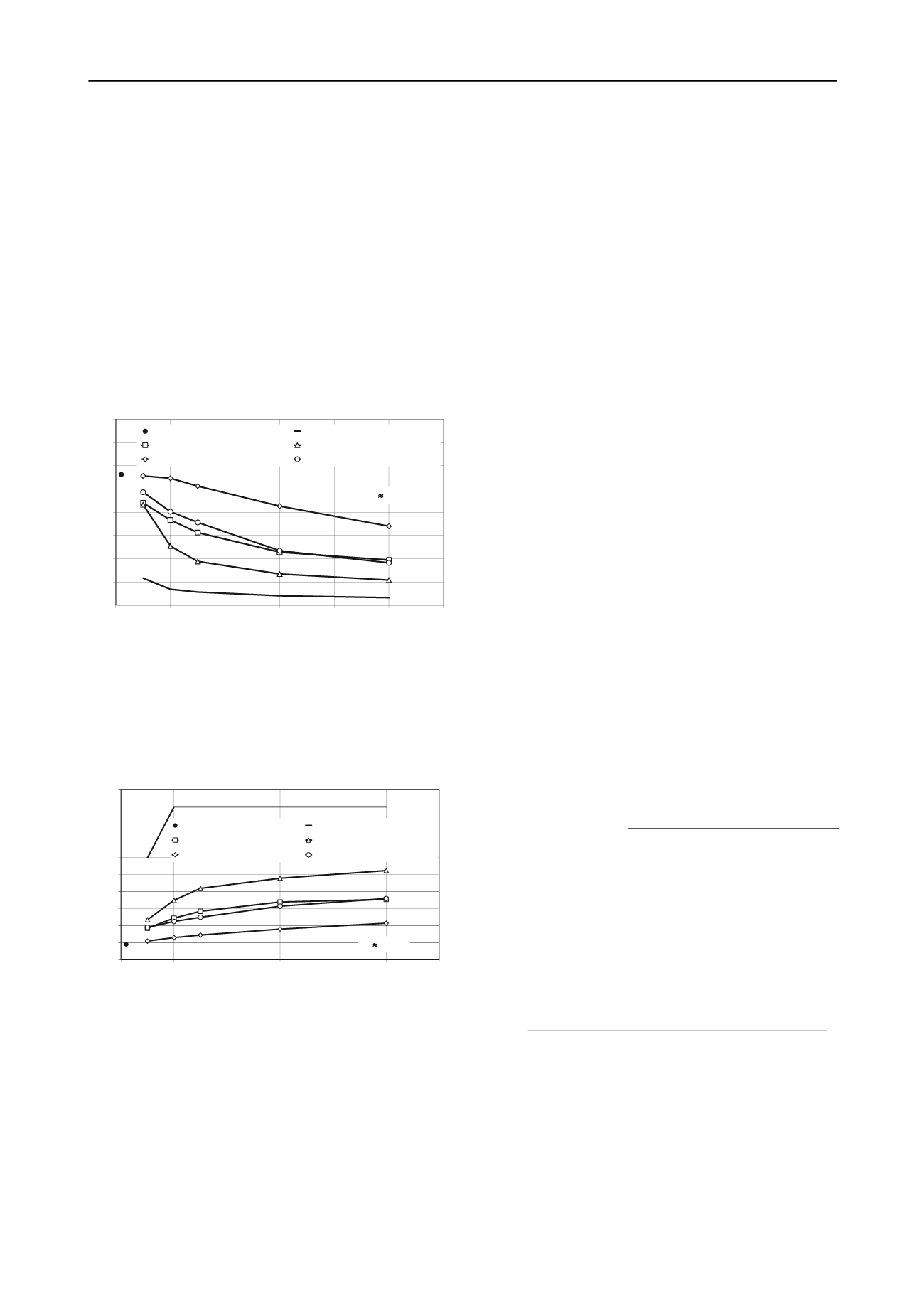
− 60-cm diameter column-type improvements reduce the
settlements linearly with increasing unconfined strength, but
not very markedly,
− 60-cm diameter columns are more effective in 2.0×2.0-m
grid spacing than in 3.0×3.0-m, although the settlements are
halved at
q
u
= 1 MPa for the larger grid as well,
− there is little difference between the reduction curves of the
60-cm diameter columns in 2.0×2.0-m grid spacing and of
the 1,8-m diameter equivalent columns made in 5.4×5.4-m
grid spacing,
− the improvement with 1,8 m diameter equivalent columns in
3.6×3.6 m grid spacing is dramatic, the settlements are
halved at about
q
u
= 0,2 MPa,
− total mass stabilization can be the most effective techno-
logy. Even for very small unconfined strengths (
q
u
= 0.1
MPa) the settlements are reduced to one-fourth.
0
5
10
15
20
25
30
35
40
0,0
0,2
0,4
0,6
0,8
1,0
1,2
settlement
s
[cm]
unconfined compressive strength
q
u
[MPa]
without treatment
mass stabilization
5.4×5.4 m square grid - d=1.8 m 3.6×3.6 m square grid - d=1.8 m
3.0×3.0 m square grid - d=0.6 m 2.0×2.0 m square grid - d=0.6 m
E
70
·
q
u
Figure 10. Calculated relationship between
s
- q
u
3.3 Stability analysis
The influence on sliding stability was evaluated by plotting
safety factor as a function of unconfined strength (Figure 11.).
For untreated soil,
SF
=
1.18 and it could be significantly
increased with even a slight amount of treatment.
1,0
1,2
1,4
1,6
1,8
2,0
2,2
2,4
2,6
2,8
3,0
0,0
0,2
0,4
0,6
0,8
1,0
1,2
safety factor
SF
[-]
unconfined compressive strength
q
u
[MPa]
without treatment
mass stabilization
5.4×5.4 m square grid - d=1.8 m 3.6×3.6 m square grid - d=1.8 m
3.0×3.0 m square grid - d=0.6 m 2.0×2.0 m square grid - d=0.6 m
E
70
·
q
u
Figure 11. Calculated relationship between
S
F –
q
u
The results can be summarized in the following:
− the lines for different diameters and grid spacing are very
similar (except for mass stabilization),
− the four lines show that for
q
u
> 0.5 MPa, improvement is not
necessary,
− the 0.6-m diameter columns with 3-m grid spacing is the
least effective just reaching
SF
=
1.4 value with the
maximum strength investigated,
− the most effective technology to insure stability is the partial
mass stabilization. With 1.8-m diameter equivalent columns
and 3.6-m grid spacing, the required
SF
= 1.35 value can be
achieved with even small unconfined strength,
− the line for total mass stabilization shows a very different
behavior. It generates a high safety factor even for small
strength values, but quickly reaches a plateau. Beyond this
point the mechanics of the stability failure changes with the
failure surface travelling through the embankment slope
only.
4 CONCLUSIONS
For road and rail embankment foundations, soil improvement is
a frequently-used technique. Column-type deep-mixing and
mass stabilization are effective soil improvement technologies
to reduce settlements increase safety against slope failure. To
prepare new railway rehabilitation projects the usability of both
methods was investigated on a special soil type: chalky silt in
Sárrét (Hungary).
While the underlying chemistry may be complex, the
performance of the mixed material can be evaluated by standard
laboratory and field tests. Laboratory tests have clearly
demonstrated that the Sárrét chalky silt is suitable for
improvement by cement. While it cures relatively slowly, an
adequate strength is reached in about 40 days. Unconfined
strengths up to 1,0 MPa can be reached by adding relatively
small amounts of cement. Its uniform and predictable response
to treatment allows the engineer to design the field
improvement. For example, the relationship between
unconfined strength and total water-cement ratio can be
described with simple equations. The Young’s modulus of the
chalky silt can be calculated as 70 times the unconfined
strength.
Finite element modeling was used to study the effectiveness of
the mixing improvement. Column-type and mass stabilization
scenarios were analyzed using strength and compressibility
values from laboratory test results. Both technologies showed
reductions in settlement and increase in stability. Based on the
figures presented, the effectiveness of various solutions can be
evaluated at the first design stages easily and rapidly. Using the
trends from the figures, an optimal solution can then be arrived at
during the detailed design phase by making only some
calculations with PLAXIS for the actual design conditions.
In the future, a further refinement of the proposed method can
be achieved by assessing and involving the cost-effectiveness of
the alternatives in the design.
5 REFERENCES
Allu Stabilisation System,
-
system
Brinkgreve R.B.J., Vermeer P.A. (2010):
PLAXIS-Finite element code for
soil and rock analyses,
Plaxis 3D. Manuals, Delft University of Techno-
logy
Plaxis bv, The Netherlands.
Dumas, C. et. al. (2003):
Innovative Technology for Accelerated Const--
ruction of Bridge and Embankment Foundations in Europe,
FHWA-
PL-03-014, 2003, pp. 6-13.
Filz, G.M., Hodges, D.K., Weatherby, D.E. and Marr, W.A. (2005):
Standardized Definitions and Laboratory Procedures for Soil-Cement
Specimens Applicable to the Wet Method of Deep Mixing,
GSP 136
Innovations in Grouting and Soil Improvement, ASCE Geo-frontiers,
Reston, Virginia, pp.1-13.
Hayward Baker, (2010) Geotechnical Construction, Construction Tech-
niques,
Logar, J. (2012),
Ground Improvement State of the Art in South Eastern
Europe
, 2. Symposium Baugrundverbesserung in der Geotechnik am
13. und 14. September 2012 an der TU Wien, pp. 19-46.
Moseley, M.P., Kirsch, K. (2004):
Ground Improvement,
Taylor and
Francis, London, pp. 57-92, 331-428.


