2516
Proceedings of the 18
th
International Conference on Soil Mechanics and Geotechnical Engineering, Paris 2013
Nevertheless, below the embankment, there is no concrete slab
or rigid structure like for the foundation of the bridge.
Reinforced earth with galvanized steel was designed to hold the
large horizontal forces of active earth pressure. Because of the
large geotextile deformations during the consolidation period, as
shown in the following monitoring results, the decision was
made to use a stronger more rigid construction with nearly no
deformation. Compared with plastic geotextiles, the steel grid
material has only very small elastic deformations, and as a
result limiting the horizontal deformations of the embankment.
Through the addition of some gravel in parts of the sandy load
transfer platform LTP, the friction between LTP and CMC was
greatly increase and nearly no deformation was necessary to
mobilize the friction of the LTP.
5.2
Controlled Modulus Columns CMC
Several measurement systems were installed between the CMC
and the reinforced earth in the load transfer platform. The
instruments show an almost perfect full stress concentration of
the load on the CMC and less than one centimetre of horizontal
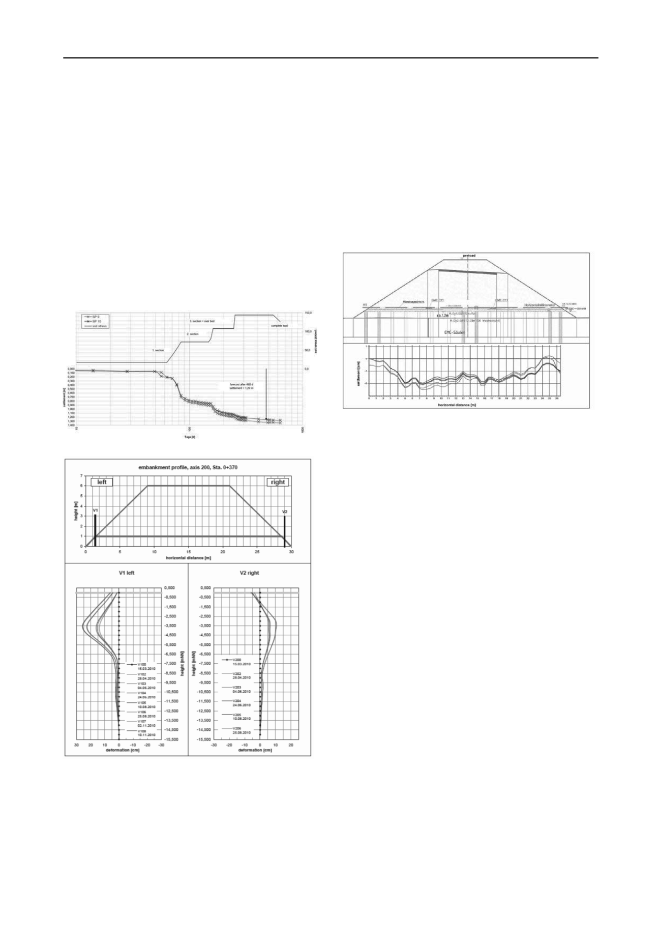
deformation. Figure 10 shows the cross section and the 5
vertical deformation measurements over a period of 2 years.
The horizontal inclinometer was laid across six marked CMC-
columns (figure 1 and figure 9). A settlement of one centimetre
of the top of the CMCs and two centimetres in-between CMC in
the reinforced earth steel construction were measured. There
was a good agreement between the calculated values of the
settlement and the results of the monitoring.
F
igure 10. horizontal inclinometer results with arround 1 cm of CMC
settlements and 2 cm of reinforced earth settlements
5 MONITORING RESULTS
5.1
Wick drains
Figure 8. measurement at the settlement plates SP 9 und SP10.
6 SUMMARY AND CONCLUSIONS
F
igure 9. vertical inclinometer results at the 7 m high damm with drains
and 600 kN/m vowen geotextile
Soft and fat clay were found at the B5 / B202 road crossing.
Additional soil investigations and laboratory tests were
performed to be able to complete a proper design, regarding
stability and consolidation time.
Oedometer consolidation tests allowed to precisely predict the
movements during the consolidation processes that were
accelerated by the use of vertical drains at different spacings.
Large deformations of up to 1.5 m of settlements and 27 cm of
horizontal displacement were experience and closely match the
calculations and show that it was the right decision not to place
the highest embankment directly on the softest soil beside the
bridge over the running traffic on the highway B5.
Vibration free CMC in combination with reinforced earth
allowed to construct this high embankment with less than two
centimetre differential settlements to the piled bridge.
With a careful planning of the work within the overall
construction schedule, detailed design combined with an
extensive monitoring program, economic soil improvement
techniques can be combined with deep foundations in one
project even on very soft soil can be treated successfully.
7 REFERENCES
DIN Deutsches Institut für Normung, 2002, DIN 4094-4: Subsoil –
field testing – part 4 : Field vane test.
DIN Deutsches Institut für Normung, 2001, DIN EN 12699: Execution
of special geotechnical work - Displacement piles; German version
J-L Chaumeny, J.F.Kirstein, S. Varaksin, 2008, An experience of
consolidation of extremly soft mud for one of Europe’s largest
projects “The AIRBUS A-380” factory in Hamburg, Glasgow.
The measured settlements during the consolidation process in
figure 8 follow very closely the predictions shown in figure 7.
An additional strong geotextile layer of 600 kN/m tensile
strength between the embankment and the vertical drains had
27 cm of deformation measured with vertical inclinometers.


