2515
Technical Committee 211 /
Comité technique 211
to pass the intermediate sandlayer in order to place the vertical
drains in the glacial sand below the second layer of soft soil.
The small spacings in this project were justified by the step
loading and the presence of fat clay in the upper layer of soft
soil with special low permeability and corresponding primary
consolidation coefficient.
3.2
Controlled Modulus Columns CMC
The controlled modulus columns CMC are well adapted to
installation in soft soils. The full displacement auger acts as a
casing and maitain the right borehole diameter over more than
two meter length. Concrete pressure and adequate volume are
monitored and maintained throughout the concreting phase,
which is very critical in very soft soils. The typical piling
standards give a minimum limit of 15 kN/m² undrained shear
strength to use for cast-in-place-concrete.
By the standard DIN EN 12699 (Deutsche Institut für
Normung 2001) above c
u
= 15 kN/m² the minimal distance
between full displacing elements is linked to the undrained
shear strength of the soils. Critical distance is only relevant
during the concrete curing period.
Compared to vibrating techniques, CMC are usually faster to
install and can be performed in softer soils with lower undrained
shear strength. There are several references with CMC-
installation directly adjacent to freshly grouted CMC under
c
u
< 15 kN/m² conditions. In this project the CMC have been
first successfully checked under conditions with the lowest c
u
-
values by integrity tests and dynamic pile tests. Loads larger
than 500 kN could be tested with a factor of safety larger than 2
FOS on the CMC, drilled into the glacial sand layer.
On part of the project, the process of installing additional
CMCs close to nearby fresh CMC was improved through the
installation of vertical drains in-between the CMC. Immediately
after the CMC installation the water starts to flow out of the
vertical drain even at the top of the sandy working platform. A
continuous flow for several hours up to one day and the volume
of water collected show an efficient fast additional
consolidation.
Compared with other CMC areas the heave of the working
platform and the excessive over-consumption of concrete,
normally increasing with the thickness of softsoil, could be
reduced by the additional intermediate vertical drains.
Figure 4. installation of CMC combined with vertical drains and pore-
water on the platform
4 CALCULATIONS AND PREDICTIONS
4.1
Consolidation and stability calculations in the areas
receiving vertical drains
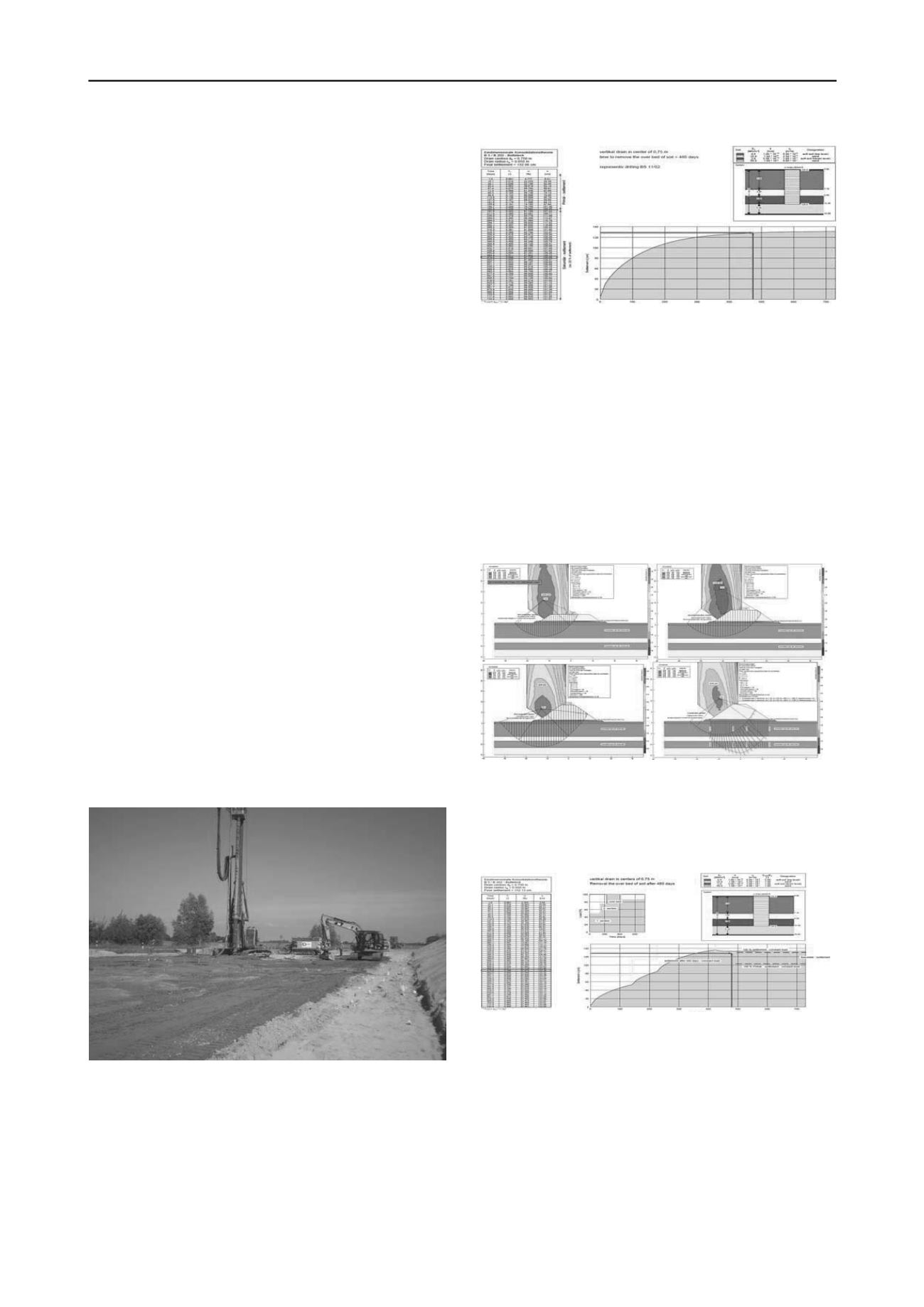
Initially, a total settlement of 1.29 m was calculated in the area
west of the bridge. The time-settlement curves for both primary
and secondary consolidation are shown below on figure 5.
Figure
5.
129 cm of settlements within ½ year of primary consolidation
with vertical drains spacing of 0.75 m
The stability calculations are based on undrained shear
strength c
u
and required to build the embankment in three steps
of loading with berms and twice waiting for the sufficient
degree of consolidation necessary. According to (Chaumeny,
Kirstein and Varaksin 2008) the shear strength was calculated
using the following relation to the degree of consolidation:
τ = U (σ tan φ'+c) + (1-U) c
u
(1)
U:
degree of consolidation
σ:
total load at a given depth
φ':
internal friction angle
c:
final drained cohesion
c
u
:
undrained shear strength
Figure 6. stability calculation of three loading steps and control
calculation of the final situation
For this project c = c
u
in formula (1) as improvement Δc
u
was added to the basic c
u
value in the stability calculations.
Δc
u
= U σ tan φ' (2)
Figure 7
.
settlement calculations with the three load steps
Field measurements and the stability analysis in final
configuration based on φ', c and porewater pressure were in
good agreement with the calculations using the improved
undrained shear strength.
4.2
Controlled Modulus Columns CMC
Due to the presence of very soft soils, the CMC are designed to
take the full load of the embankment, neglecting the small load
bearing capacity of the soil in between the inclusions. With
500 kN characteristic load per CMC, the calculated settlement
at the top of each CMC is very similar to the settlement of the
piles under the bridge.


