2514
Proceedings of the 18
th
International Conference on Soil Mechanics and Geotechnical Engineering, Paris 2013
Due to stability and settlement calculations the foundation
works took place according to the following sequence of works
and according to the figure 2 below:
1. Installation of vertical drains in different spacings from
a one meter thick sand working platform.
2. Preloading with three load steps with a distance of 30 m
security and working space from the bridge and
existing highway B5. (A)
3. The measured consolidation settlements shown in figure
8 fit with the given predictions according to figure 7.
An additional strong woven geotextile layer of 600
kN/m tensile strength between the embankment and
vertical drains had very little influence on the vertical
inclinometer results with 27 cm of deformation as
shown in figure 9.
4. After waiting for 1.3 m settlement (figure 8) a part of
the embankment and preload was temporarily rebuilt
in order to install the controlled modulus Columns
CMC. (B)
5. The preload was brought back to the edge of the
foundation systems between CMC and vertical drains
area in order to optimize the settlement behaviour.(C)
6. Installtion of deep foundations for the bridge took place
on driven concrete piles with additional sleeves
sockets in the soft soils.
7. The CMC were installed between the driven piles
afterwards, free of vibrations.
Figure 2. steps of consolidation and construction
The working sequence with different steps was necessary
because of stability calculations and the wide influence of the
settlements during the consolidation. The CMC brought the
following advantages:
- short installation period to complete the project on time
- the vibration free technique allows to work close to the
piles of the bridge
- The settlements of the embankment support on CMC
with a stiff load transfer platform are compatible with
the bridge abutment
2 SOIL-PARAMETERS
After the first part of the soil investigations with several borings
(BS) and cone penetration tests (CPT) it was clear that there
was a problem of stability and consolidation time due to the
presence of fat clay in the upper soft soil layer. The project can
be modelled with two layers of soft soils divided by a loose
sand layer in between. This reaches 13 m up to 22 m in the
deepest parts from the surface.
The undrained shear strength c
u
in the soft soil from the
results of shear vane tests multiplied with factors of 0.5 to 0.65
are linked to the plasticity according to Bjerum standard DIN
4094-4, Part 4 (Deutsche Institut für Normung 2002). In additon
to borings, several laboratory testing ( water content, organic
matter and plasticity index ) as well as several load-settlement
tests were performed.
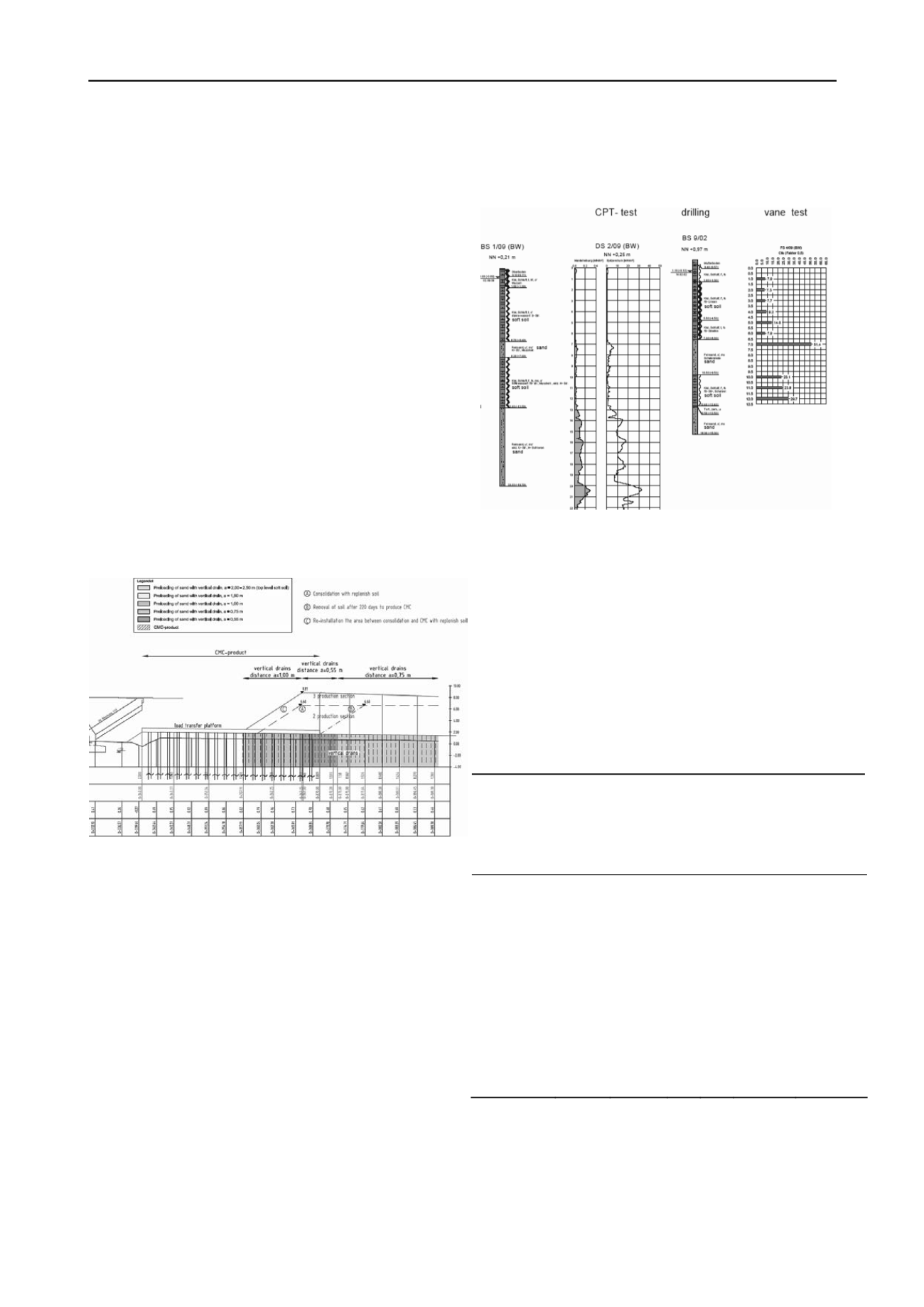
F
igure 3. boring, cone penetration test and shear vane test in the detail
area bridge west
The vane tests showed an undrained shear strength of c
u
= 6
to 8 kN/m² near the bridge and an undrained shear strength of c
u
= 12 to 20 kN/m² in other parts of the project. This was one
more reason to select a CMC foundation nearby the bridge in
the area of the lowest undrained shear strength.
Following this decision and the results of soil investigation
and laboratory the geotechnical engineers assumed an undrained
shear strength of c
u
= 12 kN/m² in vertical drain areas. The
representative soil parameters for the calculation of
consolidation and stability in the project are given in the
following table.
Table 1 . soil parameters for the calculation of consolidation and
stability in the coloured drain areas
soil
properties /
soil
density
γ
k
/γ
k
’
[kN/m
3
]
shear
strenght
φ’
k
[grade]
Cohesion
C’
,k
C
u,k
[kN/m²]
Modulus
E
s,k
[MN/m²]
50-100
kN/m²
Consoli-
dation
coeffi-
cient
c
v
[m²/s]
fill
sand
18/10
30,0
---
60
6,0*10
-1
soft soil, clay
[top level]
14/4
17,5
15
12
0,8
8,0*10
-9
soft soil, silt
top level
15/5
20,0
10
12
0,8
2,0*10
-8
sand
18/10
27,5
---
25
2,5*10
-3
soft soil, silt
(Bottom
level)
16/6
20,0
10
20
2,0
1,0*10
-7
3 SOILIMPROVEMENT TECHNIQUES
3.1
Vertical drains
Prefabricated vertical drains were installed in different spacings
with lengths between 15 m (corresponding to the conditions in
figure 3) and 22 m in other parts of the project. It was necessary


