2442
Proceedings of the 18
th
International Conference on Soil Mechanics and Geotechnical Engineering, Paris 2013
(d)
(b)
(a)
(c)
(b)
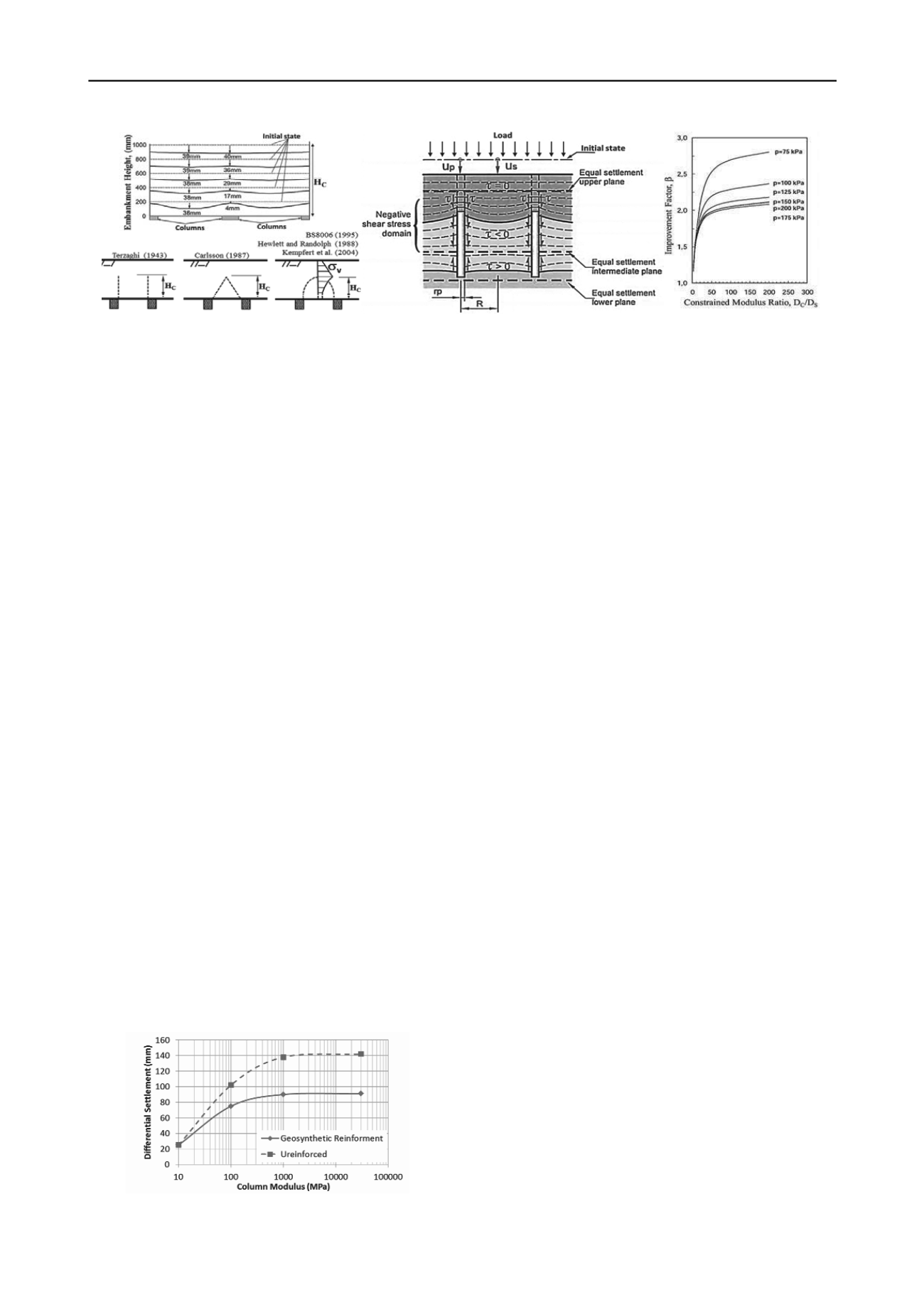
Figure 2. Mechanism of load transfer in the CSE: (a) approaches of arching-effect shape; (b) resultsof laboratory test performed by Chen et al.
(2008); (c) load transfer mechanism proposed by Combarieu (1974, 1988); (d) influence of confined modulus on improvement factor (Kirsch 2004).
These kinds of columns, with predominantly round cross-
sections of 25 cm to 80 cm diameter, are denominated Rigid
Inclusion according to the French national research project
ASIRI (Améliorations de Sols par Inclusions Rigides). Rigid
inclusions may be arranged in a regular grid, although, due to
horizontal stresses sometimes have to be distributed in wall or
panel form in order to overcome slope and internal instability.
2.2 Load Transfer Platform
The design and operation of CSE is largely influenced by the
load transmission mechanism toward the columns, through a
Load Transfer Platform (LTP) laid out at the base of
embankment. LTPs are generally composed by a layer of
compacted granular material that in many cases has to be
reinforced by geosynthetics, or composed by layers treated with
hydraulic binder.
LTP behavior is essentially determined by two parameters.
The efficacy or efficiency E, defined as the ratio between load
on the column head Q
P
and the total load on the surrounding
soil within a unit cell (W + Q), where W is the weight of
embankment and Q is the force due to surcharge on the surface;
and the critical Height H
C
, which indicates the height of
embankment where differential settlements in between column
head and middle of the grid are negligible. As stated by several
authors, E and H
C
depend on many factors such as column
rigidity, shear strength of LTP layers, spacing between columns,
and soft soil stiffness (Zaeske and Kempfert 2001, Okay 2010).
Most theoretical methods focus on the requirements of the
geosynthetic within LTPs for piled embankments, considering a
void between rigid elements. The geosynthetic takes the load
that remains in the middle of columns and delivers it to the
column heads by means of membrane effect. Consequently
almost all load is acting on the columns heads. According to
these methods only a minor part or even any soil reaction is
considered. Several guidelines or recommendations documents
deal with these methods (BS8006 2010, EBGEO 2010, Nordic
Handbook 2005). Such approaches could be classified
according to the shear stress form-distribution that governs the
mechanism of arch load-transfer and differential settlements
within the LTP (Han and Colling 2005), see Figure 2a.
According mentioned approaches H
C
varies from 0.7 to 1.6
times the clear distances between columns (s - a).
Otherwise, the method proposed by Combarieu (1974,
1988), and adopted in the ASIRI Recommendations, deals not
only with the load transfer into LTP but also along the entire
length of rigid columns. Furthermore, ASIRI project's
recommendations are based on various physical and numerical
modelling (Jenck 2005, Chevalier et al. 2008). 1º
Figure 2c shows the mechanism of load transfer proposed in
the ASIRI, where differential settlements between soil and
columns produce negative skin friction in the upper part of the
column; at certain depth where settlements are the same in soil
and columns, the skin friction is equal to zero, and below this
neutral plane the load in the columns is transferred through
positive skin friction and tip resistance. It can be noted that such
mechanism is quite similar to those exhibited by the combined
pile-raft foundations (CPRF).
3
INFLUENCE OF THE COLUMN CHARACTERISTICS
3.1 Columns stiffness
Unfortunately, so far there is not any analytical method
(commonly used) that takes into account the variation of
column stiffness, and accordingly numerical modelling usually
have to be performed to analyze the influence of column
stiffness. However, even the most relevant numerical modelling
that can be found in the literature has no focus on the risks and
suitability aspects related to the column stiffness.
Kirsch (2004) analyzed the influence of the ratio between
confined modulus of columns and soil on the improvement
factor
ratio of settlements with and without improvement).
Results indicate that confined modulus ratios beyond 40 to 50
do no suppose considerable increments on improvement factor
, (Figure 2d). Similarly, Gangakhedar (2004) performed a
numerical analysis of the influence of Young’s modulus of the
columns, on the differential settlements at the base of
geosynthetic reinforced embankment. Figure 3 shows that
differential settlements increase with increasing column
modulus. Although it can be noted that there exists a greater
increase of differential settlements when modulis are higher
than those usually obtained for stone columns, of about 80 to
120 MPa, and that differential settlements tends to be much
higher with the increase of column modulis if no geosynthetic
reinforcement is considered.
Figure 3. Influence of column modulus on the
differential settlements within Load Transfer Platform
(Gangakhedar 2004).
Therefore, the cost-operating inefficiency of columns may
be stated when column modulus are higher than 120 MPa, or
modulus ratio are larger than 40 to 50, approximately. If
columns rigidity exceeds this limits, CSE system requires an
increase on the capacity of geosynthetic-reinforcement and the
additional improvement is negligible.
It is well known that stone columns have a load-carrying
mechanism by lateral bulging, whereas rigid inclusions transmit
the load by skin friction and punching effect on their tip and
head. In the latter case, the usual amount of differential
settlement obtained in the column head implies a behavior
controlled by its ultimate limit state (ULS), and governed by
mobilization of negative skin friction. Figure 3 depicts that such


