2438
Proceedings of the 18
th
International Conference on Soil Mechanics and Geotechnical Engineering, Paris 2013
build models and the Z_Soil software was used for
computations. An elastic – ideally plastic model of Coulomb –
Mohr boundary surface with non-associated law of flow were
adopted to describe the mechanical behaviour of the soil
environment and the jet grouting columns material.
To perform computer simulations it is necessary to give the
following parameters: angle of internal friction
Φ
, angle of
dilatancy
Ψ
, cohesion
c
, modulus of elasticity
E
and Poisson’s
ratio
ν
. Values of parameters for soils building the model
subsoil were taken based on in situ tests on a test site. The
following values were taken, for sand:
E
= 55.5 MPa,
ν
= 0.3,
Φ
= 31.8°,
c =
1 kPa, for a cohesive soil interbedding:
E
= 33.8
MPa,
ν
= 0.3,
Φ
= 18.0°,
c =
30 kPa. The value of angle of
dilatancy was introduced from the range of values
Ψ
=
(0.35÷0.40)·
Φ
. Determination of material parameters for a
cement
soil material depends on the subsoil ground
characteristics, cement type in the grout, the method of columns
performance. To determine them it is necessary to take core
samples from the column performed (Fig. 1). These samples are
then tested for uniaxial and triaxial compression. For the needs
of this study 10 samples were tested for each case, obtaining
results of significant scatter (Bzówka 2009). A statistical
analysis of result values was carried out and after approximation
with the first type regression function the following parameters
were taken for calculations:
E
= 9888 MPa,
ν
= 0.186,
Φ
=
59.3°,
c =
1772 kPa. Values of soil parameters
(E
,
ν
,
Φ
,
c
) were
taken for the contact zone based on CPT sounding performed in
this area. Their values equal to soil parameters reduced by 1/3.
Figure 1. Core samples for strength tests (Bzówka, 2009).
A 2D model was built cutting from the space around
columns an area large enough, allowing idealisation of
boundary conditions. Boundary conditions were taken in the
form of: full fixing of the base of the half
space cut and partial
fixing, allowing a vertical shift, on side surfaces of the half-
space
In the model of a flat system a group of 3 columns was
taken, each of them 4.0 m long and 0.8 m in diameter, arranged
at a distance of 2.5 m, while the subsoil is stratified. Division
into quadrilateral isoparametric elements was assumed. The grid
was concentrated in the area of contact zone. An incremental
load (uniform for all columns) was applied to such system,
reflecting a real transport embankment 4.0 m high, laid at fixed
intervals in layers 0.5 m thick.
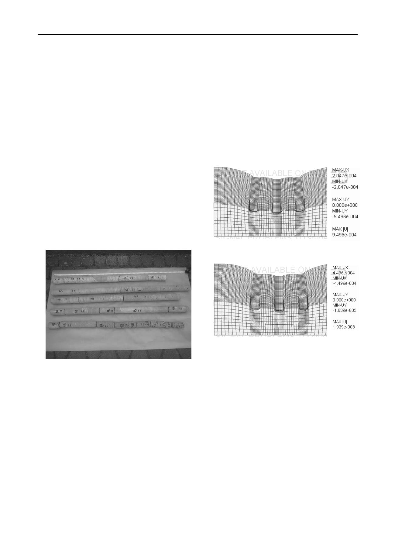
The image of system deformations caused by columns
loading is presented for two stages in Fig. 2. Corresponding
stresses are shown in Fig. 3. The stress maps perfectly show the
range of transition zone, which parameters affect the
distribution of internal forces values in the system (Bzówka et
al. 2012; Juzwa 2012a).
2 GEOMETRY OF JET GROUTING COLUMNS
The shape of columns made by the jet grouting technique, due
to specific nature of this technology, is very diversified and
difficult to predict. It depends inter alia on the type and
condition of soils making the subsoil, the injection system used
(single, double or triple) and on technological parameters
(injection pressure, size and shape of injection nozzles, speed of
injection rod pulling out and rotations and others) (Wanik and
Bzówka 2012).
To determine precisely the geometry of jet grouting columns
they are excavated, making their measurement and macroscopic
visual inspection possible. The shaft may have various shapes
(Fig. 4) depending on the aforementioned factors.
a)
b)
Figure 2. Model deformations [m] under influence of the load of
embankment: a) h=2.0 m; b) h=4.0 m high (Z_Soil) (Bzówka et al.
2012; Juzwa 2012a).
Fractal theories may be used to describe an irregular surface
of jet grouting columns. Using a fractal and a box dimension it
is possible to describe better an irregular shaft surface of a jet
grouting column, its shape and roughness. A more precise
description of roughness and geometrical parameters of soil
particles allows a more detailed determination of such
properties as: porosity, density and shear strength (Bzówka and
Skrzypczyk 2011).
The paper presents an example of fractal dimension and box
dimension calculation for an excavated jet grouting column
made in a single system (see Fig. 6÷8). Results of studies
presented in papers (Kawa and Wieczorek 2005; Wanik 2012a,
2012b; Wanik and Bzówka 2012) have been used.
The described jet grouting column was made in average
compacted medium sand, under which a stiff silty clay was
situated. After column excavating and cleaning, an irregular
shaft surface was disclosed and also a clear change of column
diameter on the boundary of two layers forming the subsoil (see
Fig. 5).
a)


