2430
Proceedings of the 18
th
International Conference on Soil Mechanics and Geotechnical Engineering, Paris 2013
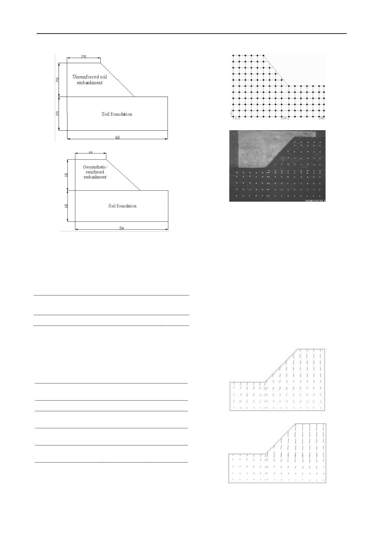
(a) 1:90 scale centrifuge model (cm)
(b) Full-scale prototype (m)
Figure 1. Arrangement of model for centrifuge test and its prototype
2.1.3
Parameters of soil and fiber
(
1
)
The physical parameters of the soil
Table 2 gives the parameters of the brown weathered shale that
obtained from compaction test and liquid and plastic limit
combined test.
Table 2. Brown weathered shale material properties
Optimm
water
content (%)
Maximm
dry density
(g/cm
3
)
Liquid
limit (%)
Plastic
limit (%)
Plasticity
index
8.9
2.15
26.928
20.193
6.735
Before the centrifuge test, soil sample was experienced
airing and grinding, then sieved by 6mm sieve to remove
impurities.
(
2
)
The parameters of the fiber
Polypropylene fiber with 19mm length was proposed to
construct the fiber reinforced soil embankment model. Table 3
gives the triaxial test strength of the embankment soil with the
fiber ratio of 1 ‰, 2 ‰ and 3 ‰ respectively.
Table 3. Embankment soil material parameters
Embankment soil
Cohesion(kPa)
Friction
angle(degrees)
Unreinforced soil
49.167
34.077
19mm-0.1%-
Polypropylene-reinforced soil
94.005
35.717
19mm-0.2%-
Polypropylene-reinforced soil
138.294
36.362
19mm-0.3%-
Polypropylene-reinforced soil
228.356
35.951
2.1.4
Deformation measuring
An array of pins was installed on the front face of the
embankment model as deformation marker. This was used for
measuring the model vertical and horizontal displacement from
coordinate difference between beginning of test and the end of
test through the front perspex window. Fig.2 shows the details
of the marked model.
(a)
(b)
Figure 2. The marked model
2.2
Centrifuge tests—summary of results
2.2.1
Comparison analysis of deformation and displacement
In this section, the results obtained from unreinforced
embankment test are compared with the results obtained from
reinforced embankment test. The deformation of unreinforced
embankment was slightly larger than the deformation of
reinforced embankment. The settlements under the shoulder of
the unreinforced embankment and the slope gradient were
considerably greater than those of reinforced embankment. Two
cracks on the top of the unreinforced embankment and (heave)
beyond the toe of the unreinforced embankment were observed
at the end of the centrifuge tests. Fig.3 and Fig.4 show the
displacement vectorgraph of unreinforced and reinforced
embankment respectively. From the close comparison between
unreinfroced and reinforced embankments, it is evident that
fiber reinforcement reduced the displacement of embankment,
and enhanced the embankment obviously.
Figure 3. Deformation of the unreinforced model
Figure 4. Deformation of geosynthetic-reinforced model


