2422
Proceedings of the 18
th
International Conference on Soil Mechanics and Geotechnical Engineering, Paris 2013
semi-analytical model. Numerical results are in agreement with
the experimental observations all along the SLT but especially
regarding to the fracture pattern: structural failure localized in
the upper part of the column. This numerical study highlights
the nonlinear behavior of the soil-mix material. In comparison
with classical “rigid” piles, the contrast of strength (and
stiffness) between the column and the soil is lower and has a
huge influence on the global behavior.
Originally, DMM was developed for GI applications in soft
clays and organic soils. But more recently, it was also dedicated
to various structural and environmental applications such as
illustrated by the following case histories.
Recently, the DMM has been chosen for several Hungarian
railway projects involving soft soils, such as the restoration of
the “Sárrét” railway line crossing an area where the subsoil
consists of soft chalky silt. For the foundation of a 4m high
embankment, two DMM were taken into account: the mass
stabilization and the soil-cement columns.
Koch and
Szepeshási (2013)
firstly describe results of laboratory tests on
chalky silt samples mixed with cement for different w/c
contents. Both DMM are then assessed using 3D-FEM
considering the site requirements in term of stability and
settlement.
In a similar way, DMM have been widely used in Japan for
the improvement of soft clays and organic soils.
Matsui et al. (2013)
introduce the concepts of an hybrid
application of soil-cement columns combined with soil mix
walls (SMW) designed for the foundation of an embankment.
The concept is illustrated in Fig. 4. The authors propose a
conceptual method allowing the control of ground deformation
and ensuring an optimization of the volume of treated soil. The
method is supported by 2D-FEM and in situ monitoring is
performed for the validation of the concept.
Ac1- 2
As2
Ac2- 2
Dvc
Ac2- 3
12.0m
7.0m
37.2m
1:1.8
6.7m
10.0m
36.2m
1.9m
4.5m
Dvs
9.8m
5.2m
21.2m
39.2m
Inside piles
Outside piles
Walls
Section view
Figure 4. GI with soil-cement columns and SMW, from Matsui et al.
(2013)
In Lund (southern Sweden) a new generation synchrotron
radiation facility, called MAX IV, is under construction.
According to
Lindh and Rydén (2013)
, it should be 100 times
more efficient than any existing comparable synchrotron
radiation facility in the world. For this kind of facility, the
vibration requirements are very stringent. Various alternatives
were discussed and simulated during the conception. The
optimum solution was achieved with a four meter thick layer of
stabilized soil below the concrete foundation. A combination of
quicklime and ground granulated blast furnace slag (GGBFS)
was found to be in agreement with both design and construction
requirements.
Jeanty et al. (2013)
describe the use of the CSM and the
Trenchmix methods for the realization of SMW. Both
techniques are explained in details and different applications are
presented, namely: settlement reduction, improvement of slope
stability, reduction of active pressure on retaining walls and
decrease of liquefaction susceptibility. The two last topics are
then illustrated with case histories.
Other case history tackles the topic of liquefaction
susceptibility restrained with the DMM.
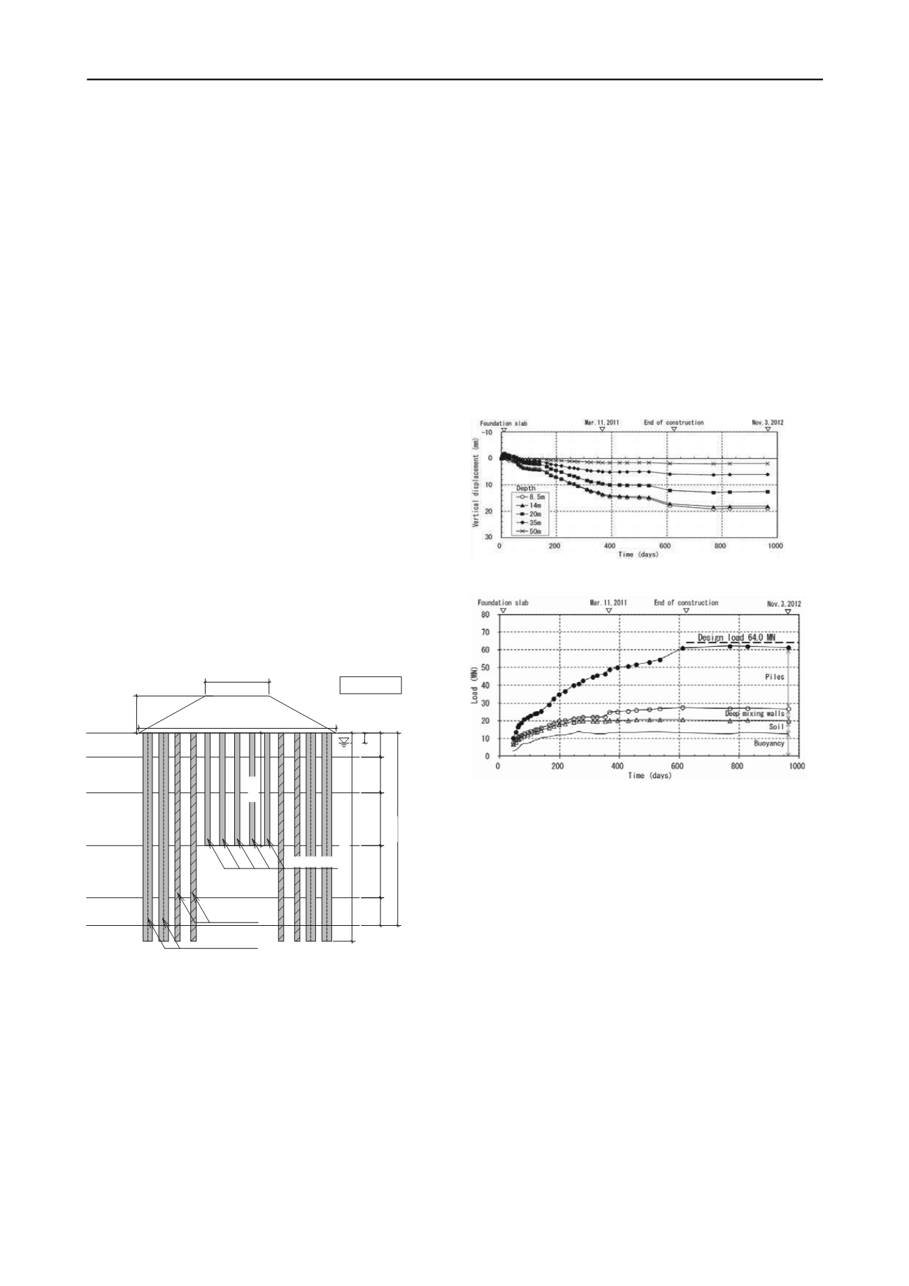
Yamashita et al.
(2013)
deal with the measurements performed underneath a
piled raft completed with SMW to reduce the risks of
liquefaction. It concerns a 12-storey office building. The load
distribution between piles, SMW and the surrounding soil has
been monitored during a period of three years. After the end of
the construction, settlements of 20 mm have been recorded, as
illustrated in Fig. 5. As another result, 70 % of the load was
taken by the piles, 14 % by the SMW and 15% by the soil, as
shown in Fig. 6. The measurements also learned that the
Tohoku earthquake of March 2011 had almost no influence on
the settlements and on the load distribution.
Figure 5. Measured vertical ground displacements below raft, from
Yamashita et al. (2013)
Figure 6. Time-dependent load sharing between raft and piles, from
Yamashita et al. (2013)
If the foundation of embankments and buildings are become
both common applications of the DMM, underpinning with soil
mix material constitutes an interesting emerging technique, such
as illustrated in the following paper.
Traditional DMM are commonly restricted for underpinning,
limitations being mainly related to the capacity of the machine
to pass existing foundation structures as reinforced slabs or
footings, the reduced working spaces and the possible low
headroom conditions.
Melentijevic et al. (2013)
present a case
history of underpinning of an existing floor slab in an industrial
building using DMM. The soil-cement columns were installed
with the new Springsol® tool. After the realization of a contact
grouting between the slab and the soil, the slab and the contact
grouting layer are cored. The spreadable Springsol® tool is then
introduced into the gap. Finally, its blades are opened and the
soil-cement column is executed until the predetermined depth.
The conception is supported by numerical modeling and
QA/QC aspects of the project are related to the testing of core
and wet grab samples.
4.2
Use of stabilized dredged material for construction
As previously discussed in Chu et al. (2009), dredging and land
reclamation have increasingly become important parts of
construction activities that involve heavily geotechnical
knowledge. If dredging provides low cost construction material,


