2413
Technical Committee 209 /
Comité technique 209
Proceedings of the 18
th
International Conference on Soil Mechanics and Geotechnical Engineering, Paris 2013
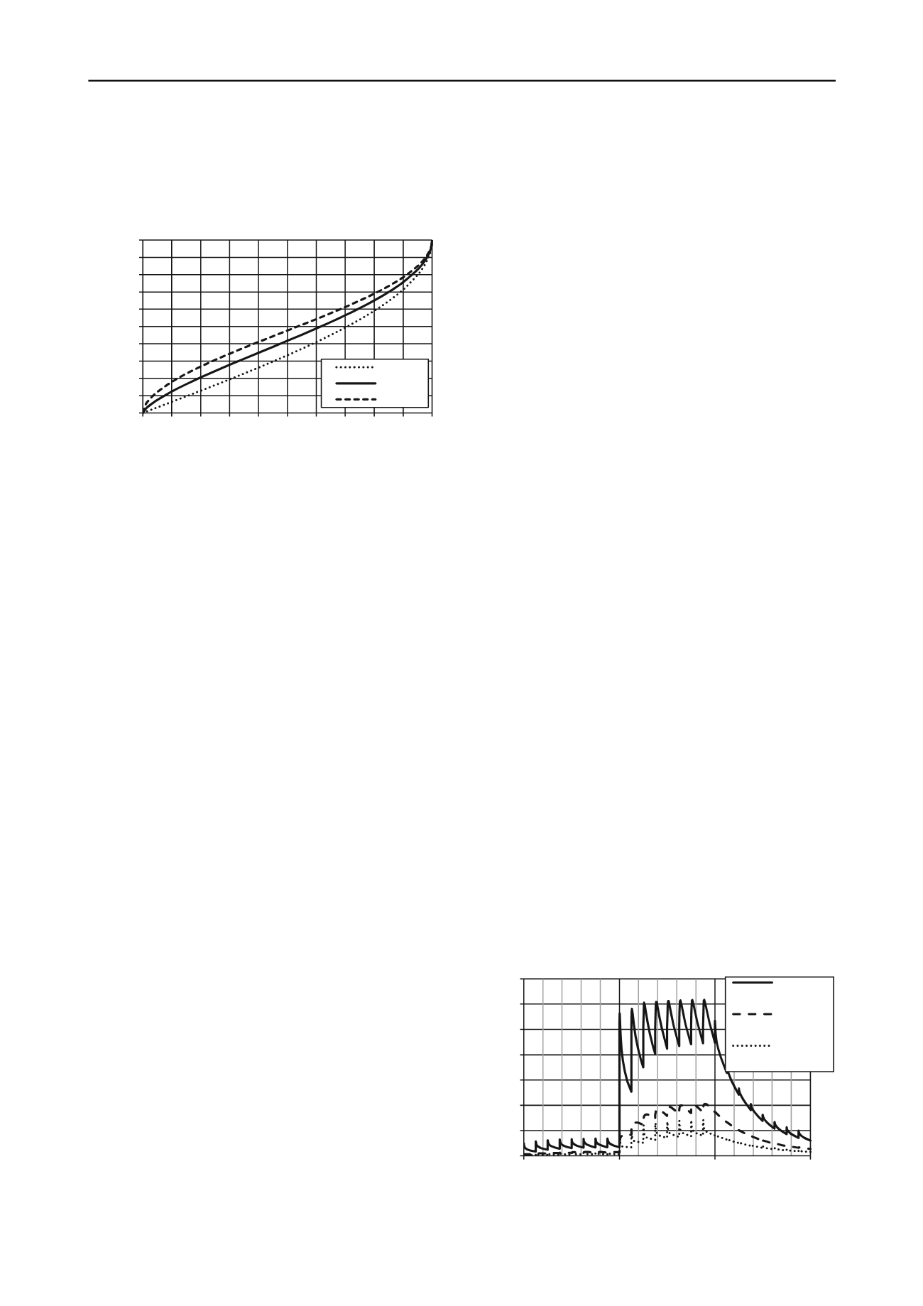
during the cyclic loading itself. This effect becomes more
important as the soil permeability increases and the loading
frequency diminishes. Not taking into account the simultaneous
dissipation leads to overestimation of the generated pore
pressure and potentially to overconservative design.
Figure 5: Pore pressure generation function.
2.3
Liquefaction of foundations
The definition of failure of a foundation due to liquefaction
requires special attention. Not all parts of the soil under a
foundation will fail at the same time or will fail at all. Some
intensely loaded zones may liquefy completely or partially,
while other zones may still be intact.
Taiebat (1999) discussed the problem and proposed the
following definitions.
Total failure
of a foundation-soil system
under cyclic loading is defined as the condition where the soil
mass deforms continuously under the ambient and cyclic loads
applied to the foundation, resulting in bearing capacity failure.
Partial failure
involves large permanent displacements during
cyclic loading. Some elements of the soil liquefy and lose their
strength, but overall, the soil mass remains stable.
Due to the complexity of the problem, numerical analysis is
often the preferred method to asses to what extent the
foundation capacity is degraded.
3 EXISTING NUMERICAL METHODS
There are at least two approaches to numerical modelling of
offshore foundation liquefaction. In the first approach an
appropriate constitutive model is used to capture cyclic stress-
strain behaviour of the soil. Many such models exist and they
can successfully reproduce soil behaviour in laboratory
conditions (e.g. bounding surface plasticity, multi-surface
plasticity). However, the number of required parameters and
calculation time are two obstacles that up to now have limited
application of these models to analysis of boundary value
problems in engineering practice.
The second approach is simpler and consists of improving a
conventional (possibly slightly modified) constitutive model by
incorporating the effects of cyclic loading separately, based on a
set of laboratory tests. A rigorous review of the work by
researchers who followed this approach to analyze offshore
foundations subjected to wave loading is given by Taiebat
(1999).
4 IMPLEMENTED METHOD
The proposed method follows the second approach and is based
on the work by Rahman et al. (1977), Taiebat (1999) and to a
lesser extent Lee & Focht (1975) and Verruijt & Song (1991).
The calculation procedure is as follows: undrained pore
pressure increases are calculated analytically, at regular time
intervals in the FE analysis. At each node, the pore pressure at
the end of the previous interval (which includes effects of all
previous loading) is converted into an equivalent number of
cycles using Eq. 2. The increase in pore pressure during next
interval (containing a number of load cycles) can then be
calculated from Eq. 2, assuming the CSR is constant during this
interval.
After the pore pressure and effective stress in the FE analysis
are updated accordingly, the dissipation analysis continues over
the length of the considered time interval. This is done in a
coupled Biot-type consolidation analysis in the FE package
Abaqus.
The total design storm consists of a number of load parcels,
during which the cyclic load (and thus the CSR) is assumed to
have a constant average and amplitude. The load parcels are
subdivided in a number of steps and the process of updating the
pore pressure and subsequent consolidation is repeated for every
subdivision, tracing the average pore pressure response
(excluding oscillations within each load cycle) over the entire
load history of the design storm.
5 APPLICATION TO SUCTION CAISSONS
In two case studies the influence of cyclic loading history and
drainage effects on the caisson performance is assessed using
the proposed model. Realistic forces acting on the foundation
are estimated from the loads outlined in section 1.2 and a
simplified load histogram is adopted. Corresponding realistic
caisson dimensions are found by applying the bearing capacity
equation (DNV 1992) for the tripod caisson and the formula
proposed by Byrne and Houlsby (2003) for the monopod
caisson. In both cases the sand is represented by an isotropic
elastic material model with Mohr-Coulomb plasticity.
5.1
Leeward caisson of a tripod
5.1.1
Model
Initially the horizontal load, divided over three caissons, is
neglected. The resulting axisymmetric problem only considers
vertical cyclic loading on the individual caisson due to weight
of the structure and overturning moments as this is the most
important load component. The histogram consists of 3 load
parcels of 2000 seconds each, applying 200 load cycles at 60%
of the maximum load in the first and last parcel and 200 cycles
at maximum loading in the middle parcel.
5.1.2
Results
An example of calculated pore pressure response within and
around a 8x8m caisson is shown in Figure 6. First of all it is
clear that the abrupt increases (generation) and gradual
decreases (dissipation) are an approximation for the real
behaviour.
Figure 6: Example of excess pore pressure history, tripod caisson
0
0.1
0.2
0.3
0.4
0.5
0.6
0.7
0.8
0.9
1
0 0.1 0.2 0.3 0.4 0.5 0.6 0.7 0.8 0.9 1
Pore pressure ratio u/u
max
Cycle ratio N/N
l
α
= 0.5
α
= 0.7
α
= 0.9
0
1
2
3
4
5
6
7
0
2000
4000
6000
Pore pressure [kPa]
time [s]
under
baseplate,
center line
skirt tip level,
center line
skirt tip level,
underneath
skirt


