2412
Proceedings of the 18
th
International Conference on Soil Mechanics and Geotechnical Engineering, Paris 2013
Proceedings of the 18
th
International Conference on Soil Mechanics and Geotechnical Engineering, Paris 2013
1.2
Loads on offshore wind turbines
The foundation must resist loads caused by the weight of the
structure, the operation of the turbine, currents, wind and wave
action. Incoming waves exert a cyclic horizontal force (and
moment) on the foundation, which in the case of offshore wind
turbines may be a significant proportion of the weight of the
structure. A vertical weight of 6MN and a horizontal wave
loading of up to 3MN are realistic values for a 3.5MW turbine
(Houlsby et al. 2005).
The offshore design standard DNV-OS-J101 (DNV 2011)
specifies that the structure must be able to resist a 50-year
design storm (a storm with a probability of occurrence of 1/50
during one year), where not only the peak loads, but the entire
history of cyclic loading affects the stability of the structure. For
the cyclic loading assessment, the irregular wave loading is
usually converted into an idealized, equivalent design storm.
1.3
Structural configuration
Caissons could support offshore wind turbines in two ways,
based on mode of load transfer to the soil (Figure 2). A
monopod foundation consists of a single caisson and is suited
for shallow waters. In deeper water, the increased moments
acting on the caisson would require a very large caisson. In that
case a tripod (three caissons) or quadripod (four caissons)
structure could be economical, as moment loads are converted
into a vertical push and pull action on the individual caissons.
Figure 2: The monopod and multipod concept and reaction forces on the
caissons
1.4
Scope of work
The aim of this paper is to examine the effect of cyclic loading
during a design storm on both the monopod and multipod and to
produce a model which is suitable for engineering practice. The
presented model is still under development, and is considered a
starting point for more sophisticated approaches.
2 CYCLIC DEGRADATION OF SOILS AND
FOUNDATIONS
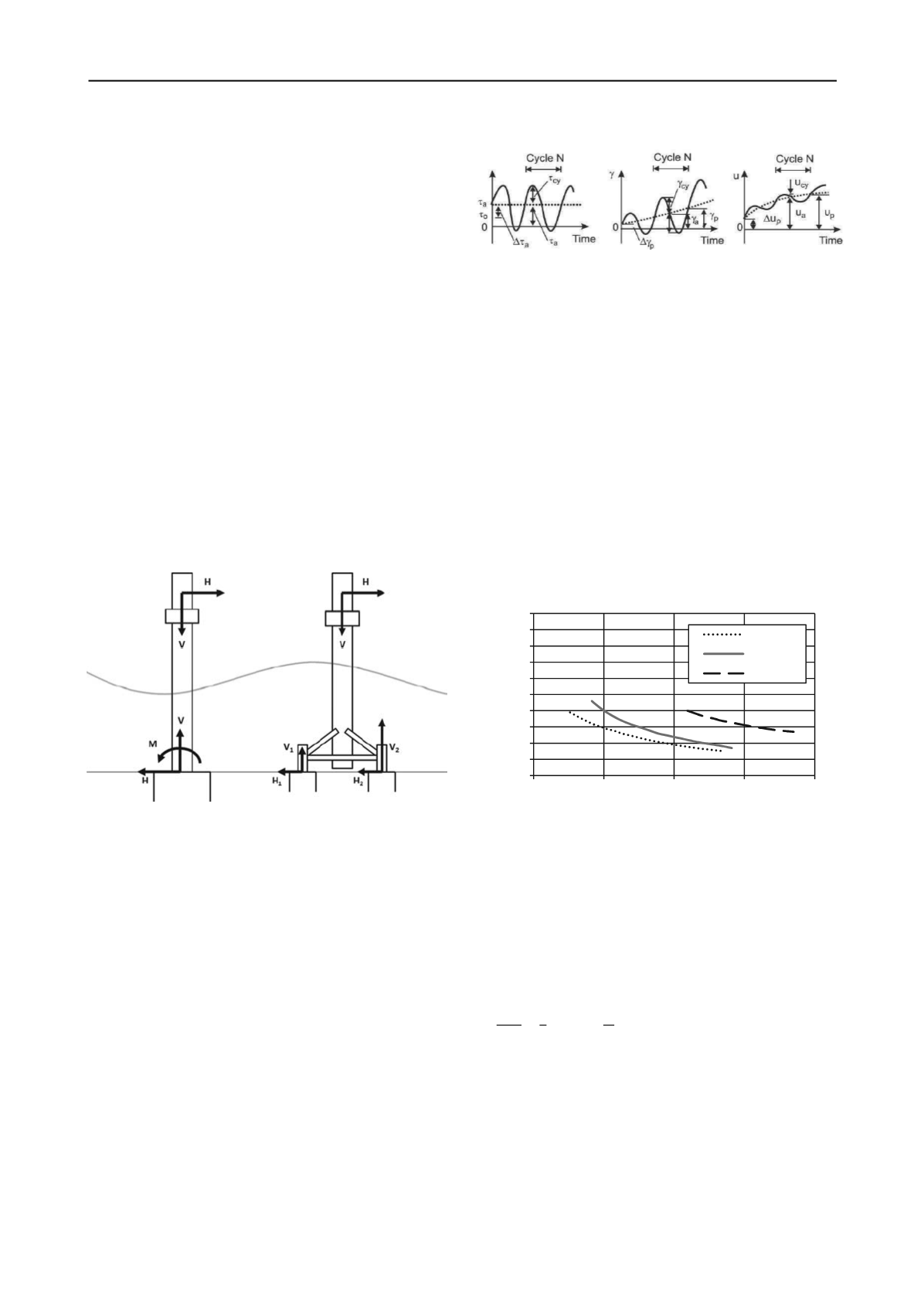
2.1
Pore pressure build up in sand under cyclic loading
Cyclic shearing of sand degrades the soil structure and causes a
tendency to densify. This is the case even for very dense sands
that are dilative under monotonic loading conditions (Seed and
Idriss 1980, Andersen and Berre 1999).
Under undrained conditions, volume changes are prevented
by the low compressibility of water, so normal stresses carried
by the soil will be transferred to the pore water, thus increasing
the pore water pressure in the sample as illustrated in Figure 3.
The decrease in effective stress furthermore causes a
progressive increase in average shear strain. Failure occurs
when the generated pore pressure reaches a critical value
u
max
.
Figure 3: Behaviour of sand under cyclic loading (after Andersen and
Berre 1999)
The intensity of cyclic loading is expressed in terms of the
cyclic shear stress ratio, the ratio of cyclic deviatoric stress
amplitude over mean effective stress. This formulation is
convenient for the interpretation of triaxial test results and for
implementation in the finite element procedure.
⁄
(1)
Based on several cyclic tests at different CSR, cyclic shear
strength curves can be established, expressing the number of
cycles required to induce failure
N
l
as a function of the CSR and
Dr.
The cyclic shear strength depends on the relative density and
the initial shear stress in the sample. The set of curves used in
this study was presented by Lee and Focht (1975) in their
investigation of the liquefaction potential at the Ekofisk site,
North Sea. The curves for this typical dense North Sea sand are
redrawn in Figure 4.
Figure 4: Cyclic shear strength curves for dense North Sea sand at the
Ekofisk site (after Lee and Focht 1975)
The build-up of pore pressure in samples can be described by
the empirically determined pore pressure generation function
given in Eq. 2 and plotted in Figure 5. The empirical constant
α
depends on the soil properties and is on average equal to 0.7
(Rahman et al. 1977). As it is cyclically loaded, the soil sample
evolves from the initial, undisturbed state at
N
= 0 to a state of
liquefaction at
N
=
N
l
and
u
=
u
max
.
⁄
(2)
2.2
Drainage conditions
In laboratory tests soil samples are brought to failure under
undrained conditions. However, in situ loading conditions may
be fully or partially drained, depending on the combination of
soil permeability, frequency of the loading and drainage
conditions.
For offshore turbines founded on sand, the high permeability
and relatively slow wave loading results in the dissipation or
redistribution of a significant part of the generated pore pressure
0
0.1
0.2
0.3
0.4
0.5
0.6
0.7
0.8
0.9
1
1
10
100
1000
10000
CSR
number of cycles to failure N
l
Dr 63%
Dr 77%
Dr 100%


