2439
Technical Committee 211 /
Comité technique 211
a)
b)
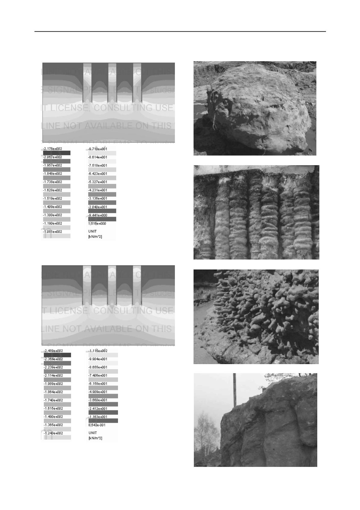
Figure 3. Map of vertical stresses of the model under influence of the
load of embankment: a) h=2.0 m; b) h=4.0 m high (Z_Soil) (Bzówka et
al. 2012; Juzwa 2012a).
a)
b)
c)
d)
Figure 4. Different shapes of excavated jet grouting columns
(photos: J. Bzówka, and K. Wanik).


