2232
Proceedings of the 18
th
International Conference on Soil Mechanics and Geotechnical Engineering, Paris 2013
case with soil removal work, case with counterweight fill, and
case with both soil removal work and counterweight fill.
5 CONCLUSION
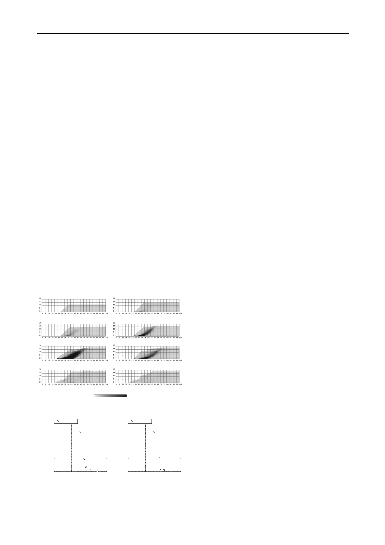
The distributions of accumulation of the maximum shear
strain are shown in Fig. 7. As explained in above, boundary
particles are used for the wall, but are not shown in these figures.
Figure 8 shows the relationship between the safety factor and
the value obtained by dividing the displacement
at the top of
the slope by the height of the slope
H
. When the safety factor is
larger than 1.0(Cases 1 and 2), shear strain does not appear in
the figures. However, when the safety factor is less than
1.0(Cases 3 to 5), a distribution of circular shear strain can be
seen. When the safety factor is close to 0.9, shear strain is
observed but still large deformation cannot be observed. In
particular, a crack forms at the crown of the slope, and block
slippage is confirmed in the cases with the lowest safety factors.
In the case without any countermeasures (Case 5), the shear
strain is conspicuous and the slope is largely deformed. On the
other hand, in the cases with countermeasures (Cases 6 to 8),
the shear strain does not become more prominent and the
displacements can be controlled as the safety factor increased.
Thus, similar tendencies are observed in the results from the
SPH method and the Fellenius method. In addition, while
conventional circular slippage calculations are used to estimate
the occurrence of rigid block slippage, the SPH method can
estimate not only the stability, but also the effects of
deformation. In Cases 3 and 7, the slope is not deformed,
although the safety factor is less than 1.0. On the boundary
between stable and unstable states, we consider that the slope is
stabilized due to the redistribution of stress following an initial
small deformation. The SPH method can estimate deformation
and stability simultaneously. Moreover, it is capable of
continuously predicting the deformation, even in a large
deformation region. In other words, the SPH method can predict
the entire deformation process of a geomaterial. Therefore, one
may conclude that a variety of useful information about slope
stability problems can be obtained via the SPH method.
In this study, introducing the constitutive model into the SPH
method, deformation analyses of geomaterials were carried out.
Firstly, in order to validate the method, the simulation of simple
shear test of elasto-plastic material was simulated using two
kinds of constitutive models of geomaterials. The numerical
results were compared with the theoretical solutions. Then, a
slope stability analysis considering countermeasures was carried
out. The conclusions can be summarized as follows:
The simulation of a simple shear test demonstrated that the
SPH method could calculate the appropriate stress state of
geomaterials using high performance elasto-plastic
constitutive models.
The SPH method was applied to slope stability analysis.
The results indicated that the method was able to express
the same safety factor tendencies obtained from the
conventional circular slippage calculations. At the same
time, the SPH method can simultaneously estimate both the
deformation and stability. From the results of a slope
stability analysis considering countermeasures, it can be
inferred that the SPH method was capable of predicting the
deformation and stability of slopes even in complex
situations,
such
as
simulations
that
include
countermeasures.
From a series of the numerical results, the SPH method was
found to be applicable to slope stability analysis. Also, the
SPH method has the potential to describe the deformation of
geomaterials from the initial state to subsequent large
deformations.
6 REFERENCES
Asaoka A. et al. 2000. Superloading yield surface concept for highly
structured soil behavior,
Soils and Foundations
, 40 (2), 99-110.
(a)Case1 (Fs=1.24
,
without any countermeasure) (b)Case2 (Fs=1.01
,
without any countermeasure)
(c)Case3 (Fs=0.91
,
without any countermeasure) (d)Case4 (Fs=0.86
,
without any countermeasure)
(e)Case5 (Fs=0.75
,
without any countermeasure)
(f)Case6 (Fs=0.87
,
soil removal work)
(g)Case7 (Fs=0.90
,
counterweight fill)
(h)Case8 (Fs=1.02
,
both countermeasures)
30%
0%
Asaoka A. et al. 2002. An elasto-plastic description of two distinct
volume change mechanisms of soils,
Soils and Foundations
, 42 (5),
47-57.
Bui, H.H. 2007. Lagrangian mesh-free particle method (SPH) for large
deformation and post-failure of geomaterial using elasto-plastic
constitutive models,
Ph.D. Dissertation of Ritsumeikan University
,
Japan.
Cudall P.A. and Strack O.D.L. 1979. A discrete numerical model for
granular assemblies,
Geotechnique
, 29 (1), 47-65.
Drucker D.C. and Prager W. 1952. Soil mechanics and plastic analysis
for limit design,
Quart. Appl. Math.
, 10 (2), 157-165.
Gingold R.A. and Monaghan J.J. 1977. Smoothed particle
hydrodynamics: theory and application to non-spherical stars,
Monthly Notices Roy. Astron. Soc.
, 181, 375-389.
Gray J.P. et al. 2001. SPH elastic dynamics,
Comput. Methods Appl.
Mech. Engrg.
, 190, 6641-6662.
Lucy L.B. 1977. A numerical approach to the testing of the fission
hypothesis,
Astron. J.
, 82, 1023-1024.
Maeda K. and Sakai M. 2004. Development of seepage failure analysis
procedure of granular ground with Smoothed Particle
Hydrodynamics (SPH) method,
J. Appl. Mech.
, JSCE, 7, 775-786
(in Japanese).
Figure 7. Distributions of accumulation of the maximum shear strain
Monaghan J.J. and Gingold R.A. 1983. Shock simulation by the particle
method SPH,
J. Comput. Phys.
, 52, 374-389.
0
0.1
0.2
0.3
0.4
0
0.5
1
1.5
Case1~Case5
/
H
safety factor Fs
0
0.1
0.2
0.3
0.4
0
0.5
1
1.5
Case5~Case8
/
H
safety factor Fs
Monaghan J.J. 2000. SPH without a tensile instability,
J. Comput. Phys.
,
159, 290-311.
Moriguchi S. 2005. CIP-based numerical analysis for large deformation
of geomaterials,
Ph.D. Dissertation of Gifu University
, Japan.
Swegle J.W. et al. 1994. An analysis of smoothed particle
hydrodynamics,
SAND93-2513
,
Sandia National Laboratories
,
Albuquerque
,
NM
.
Swegle J.W. et al. 1995. Smoothed particle hydrodynamics stability
analysis,
J. Comput. Phys.
, 116(1), 123-134.
(a)Cases 1 to 5 (b)Cases 5 to 8
Figure 8. Relationship between safety factor and displacement at the top
of slope.


