1820
Proceedings of the 18
th
International Conference on Soil Mechanics and Geotechnical Engineering, Paris 2013
positive skin friction and tip resistance, like for usual deep
foundations.
Columns used to
ensure the stability
(pile function)
Columns work as
settlement reducers
(function as soil
reinforcement)
ULS‐GEO without RI
Single footing (base failure) / Slope (failure)
Single footing (sliding)
Domain 1
Domain 2
Check
not validated
Check
validated
Usual calculation methods for single footings
and slopes (without RI)
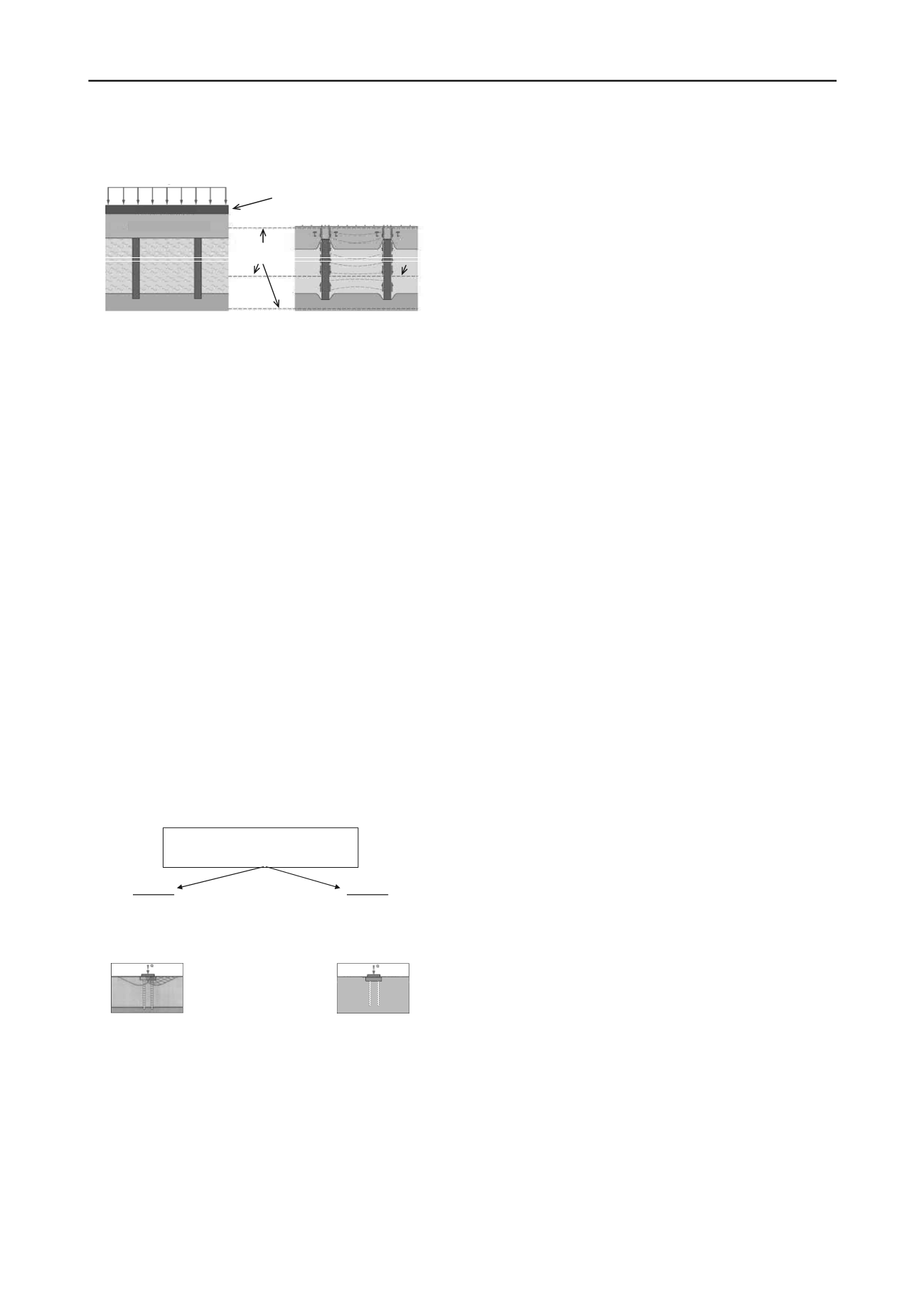
Figure 2.
Load bearing and deformation behaviour of rigid
inclusions
Horizontal loads can be supported by such systems as well,
for example in the case of horizontally loaded isolated footings
or when reinforced columns are used as nails against slope
failure.
The usual applications of rigid inclusions are the following:
•
Under large embankments or raft foundations to reduce
settlements
•
At the border of embankments (slope) and potentially of
raft foundations against slope failure, or to reduce settlements
•
Under isolated footings against failure of bearing
capacity or sliding, or to reduce the settlements
3 SAFETY CHECKS IN THE FRENCH
RECOMMENDATIONS ASIRI
First of all, the load distribution in the system without
inclusions has to be determined, using the usual calculation
methods for foundations or slopes. If the safety according to the
French standards against failure of bearing capacity, sliding or
slope failure in the ultimate limit state (ULS) is not guaranteed
without columns, the subsequent safety checks correspond to
the so-called „domain 1“ (Figure 3). Otherwise the columns can
be used only to reduce the deformations („domain 2“). The
required calculation of the load distribution with columns has to
be carried out using comprehensive numerical models or using
one of the recommended simplified models in ASIRI.
Figure 3.
Classification in domain 1 and 2 in ASIRI
In the domain 1, the safety checks are carried out in analogy
with the French Eurocode 7 application standards for deep
foundations in addition to the standards for isolated footings and
slope stability. The favourable action of the columns is taken
into account by reducing the foundation load on the soil. Then,
the checks of bearing capacity for the foundation or the slope
are carried out normally with this reduced load. Besides, the
bearing capacity of the columns has to be checked as well
against ultimate limit states (ULS) against serviceability limit
states (SLS) under the neutral plane (Figure 2), just like for piles
after the French standard for deep foundations. The structural
capacity of the columns, which are in general not reinforced,
has to be verified by means of a limitation of the compression
and shear stresses in the column section in the ULS and SLS.
The compatibility of the calculated vertical and horizontal
deformations has to be checked in SLS.
planes with equal
settlement
Load transfer layer
rigid or flexible raft foundation
(or embankement)
neutral
plane
In the domain 2, the columns are considered as pure
settlement reducers. Therefore, no check of the bearing capacity
is required in this domain, like in the design philosophy of the
CPRF-guideline (Hanisch et al. 2002) or in the case of the so-
called “creep piles”. Only SLS-checks have to be carried out
here.
In both cases, compatibility verifications have to be done
after the checks, in particular to verify the compatibility of the
stresses in the load transfer layer.
4 COMPARISON WITH STANDARDS AND
RECOMMENDATIONS
In this section, the recommended safety checks in ASIRI for the
domains 1 and 2 are compared with the French and German
piling standards and with recommendations for similar piles or
columns systems, i.e. the German CPRF-Guideline (Hanisch et
al. 2002) and the German guideline for stabilizing columns
"Merkblatt
für
die
Herstellung,
Bemessung
und
Qualitätssicherung
von
Stabilisierungssäulen
zur
Untergrundverbesserung" (CSV-Merkblatt, DGGT 2002).
Only the persistent load situation (BS-P in Germany) is
considered here. The partial safety factors for the actions in this
load case are the same in all regulations, that is 1,35
(respectively 1,5) for the permanent (respectively variable)
loads in the case of foundations, and 1,0 (respectively 1,3) for
the slope stability.
4.1 External bearing capacity (GEO)
In ASIRI, only the domain 1, where the columns are necessary
for the stability, is concerned by the safety checks in the ULS
(Table 1). The verifications correspond to those of the French
application standard of Eurocode 7 for compression piles (with
a diameter of usually 1 m up to 3 m), in general with the use of
empirical resistance values from pressuremeter tests (Table 2).
The favourable effect of the columns in the checks of the
footing or the slope is taken into account by reducing the total
load by the force taken in the columns. After ASIRI, no pile
loading test has to be done in the design phase for the
determination of the bearing capacity. However, loading tests
have to be carried out in the execution phase according to
ASIRI to verify the previously determined bearing capacity.
In the CPRF-guideline (Hanisch et al. 2002), no distinction
is made between a use as “settlement reducer” or as “resistance
increaser”. The maximum characteristic resistance is defined
here from the load-settlement curve of the global system, and
divided by a safety factor to obtain the design value (Table 3).
The bearing capacity of the piles themselves has not to be
verified, since the whole system made of the slab, the piles and
the soil has already to be stable. In the CSV-guideline on the
contrary the bearing capacity of the single columns always has
to be checked, with the additional assumption that the total
applied load from the structure is taken by the columns (here
diameter 12 cm up to 20 cm), which is on the safe side.


