1814
Proceedings of the 18
th
International Conference on Soil Mechanics and Geotechnical Engineering, Paris 2013
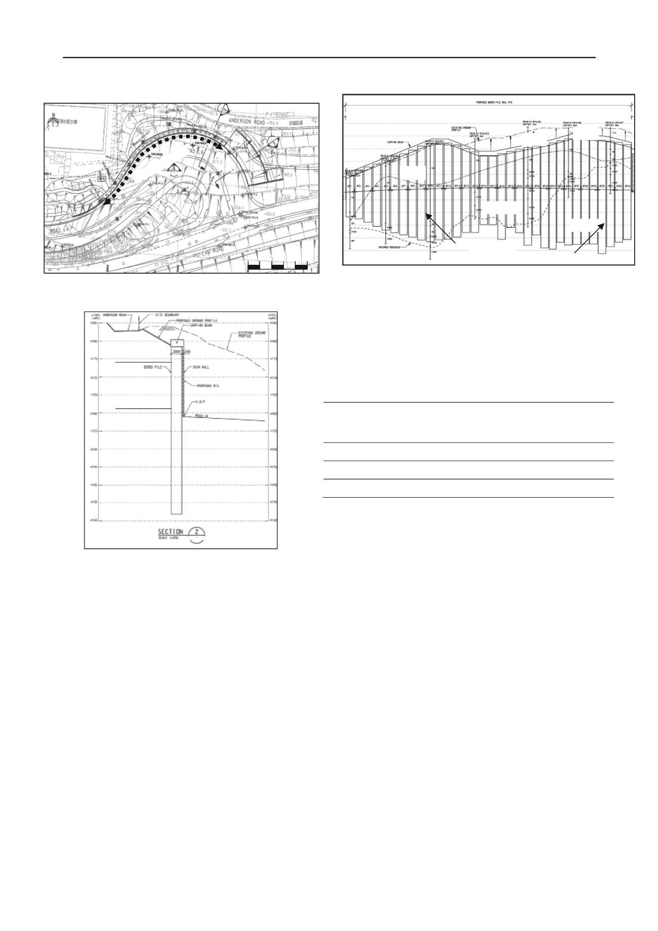
Figure 2. Layout of the bored pile wall with adjacent constraints
Figure 3. Geological section
2.2 Geological Conditions
The soil stratigraphy of the site comprises Fill and weathered
granite. The fill was generally present within the Site with
maximum thickness of fill up to 8m below existing ground
level. The fill comprises loose to medium dense, gravely silty
sand or sandy clayey silt, with some rock and concrete
fragments and occasional domestic waste. The SPT ’N’ values
ranged from 5 to 15 indicating a loose state. Completely to
highly decomposed granite is present beneath the superficial
deposits. The granites are commonly fine to medium grained
greyish pink to pinkish grey in colour in fresh state and the
granite is weathered to varying depths. The thickness of
completely decomposed granite (CDG) weathering Grade V
ranges from 5 m to 10 m with SPT-N values from 15 to 100.
Highly decomposed granites (HDG) of weathering Grade IV
occurs with SPT ‘N’ value larger than 100. The maximum
depth to moderately to slightly decomposed granites (M/SDG)
encountered ranges from 15m to 40m below existing ground
level. The uniaxial compressive strength of the M/SDG ranging
from 40 to 135mPa. A geological section along the proposed
cantilever bored pile wall is presented in Figure 4.
d (CU) triaxial tests with pore water pressure measurement
were carried out. Design lines are drawn based on engineer
M/SDG
HDG
CDG
FILL
FILL
Bored Pile Wall
SERVICE
RESERVOIR
0 10 20 30 40 50m
BP11
BP30
Figure 4. Geological long section
2.3 Geotechnical Design Parameters
FILL
CDG
HDG
The engineering properties of soils and rocks have been
assessed using the field and laboratory test data. A total of 105
nos. consolidated undraineing judgment with reference to the
‘best fit’, ‘lower bound’ and average values. The adopted
design parameters are listed in Table 1.
Table 1. Summary of adopted soil parameters
‘N’ <100
Soil
Stratum
Density
(kN/m
3
)
Cohesion,
c’
(kPa)
Fictional
Angle,
(degree)
E value
(MPa)
FILL
19
0
35
10
CDG
19
7
38
20
HDG
19
7
38
40
‘N’ >100
2.4 Groundwater levels
Piezometers and standpipes have been installed over the Site to
provide groundwater information during construction.
Generally, groundwater levels tend to be at or near the rockhead
level and typically rise by up to about 3m after rainfall. The
groundwater level is assumed to be +166 mPD on the retained
side and at the excavation level (approximately +159 mPD) at
the excavated side.
3 DESIGN OF CANTILEVER BORED PILE WALL
3.1 Design considerations
The results of analyses using the two design methods, Geoguide
1 (Second Edition) using a simplified model and CIRIA Report
No. C580, for cantilever bored pile wall are presented. These
calculations assume that the entire embedded portion of the
cantilever bored pile wall is in soil. The effect of the capping
beam is ignored in the analysis and the long term creep effect is
to be controlled by the post construction of a 500mm thick skin
wall.
3.2 Traditional Approach (Geoguide 1)
The traditional approach of the design of a cantilever bored pile
wall was carried out in accordance with the recommendation
given in Section 11.2.3 and Figure 50(c) of Geoguide 1 (Second
Edition) where a simplified model was adopted for the
determination of the embedment depth of the pile, (Pang et al
2005).


