1811
Technical Committee 205 /
Comité technique 205
a) very high design seismic loads (i.e. , level 2), as those
experienced during the 1995 Kobe earthquake;
b) design against level 2 based on residual displacement;
c) the use of both peak and residual shear strengths with well-
compacted backfill;
d) design based on the limit equilibrium stability analysis;
e) control to high backfill compaction and good drainage;
f) strong recommendation of GRS structures as highly
earthquake-resistant soil structures;
and
g) no creep reduction to obtain the design tensile strength of
geosynthetic reinforcement.
When following this design code, engineers naturally chose
GRS structures.
3.2
Geogrid reinforcement for masonry walls in houses
It is also known that a lot of causalities during earthquakes are
caused by falling bricks, when masonry walls in the houses e.g.
between steel frames are collapsing. An important improvement
of stability under seismic loading can be achieved by geogrid
reinforcement of masonry walls (Figure 4) as investigated and
developed in Germany at Bauhaus-University Weimar
(Burkhardt et al 2005).
Figure 4. Strength test of geogrid reinforced masonry wall (Burkhardt et
al 2005).
4 TSUNAMI SHELTER
When a tsunami warning is given people have to leave low
coastal areas as quick as possible. After the devastating tsunami
of 2004 in the Indian ocean in the meantime a “Tsunami Early
Warning System” is in operation. But a big challenge still is the
organization of an effective evacuation of the people living in
the endangered big cities at the coast in the available very short
time of about 30 minutes between “Tsunami Warning” and the
arrival of the tsunami wave. In Indonesia for instance “raised
earth parks” as cost effective tsunami shelter are discussed to
establish safe places right at the coast. These artificial hills have
to be high enough, stable against earthquake loading and
erosion-resistant to the wash of the tsunami wave. It should also
be easy for all people to get up to the safe top of the hill.
Structures of geosynthetic-reinforced soil (GRS structures) can
fulfil these requirements. Figure 5 is showing the idea of
“TEREP – Tsunami Evacuation Raised Earth Park” as proposed
for the city of Padang, Indonesia. For Padang five evacuation
parks are discussed, each park as refuge for 15.000 people out
of a 1.5 km radius. As of the author´s actual knowledge the
construction of TEREP is still delayed. Let´s hope that fading
away of the rembemering of the last tsunami desaster is not the
reason – the next tsunami will come!
Figure 5. Idea of “Tsunami Evacuation Raised Earth Park” for the City
of Pandang, Indonesia (Tucker, 2010)
.
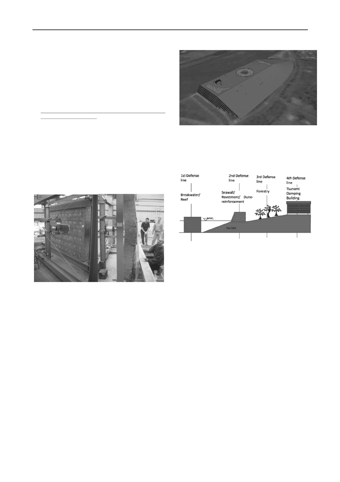
Tsunami defense systems can be separated into different
“defense lines” as shown in Figure 6 (Recio, J. and Oumeraci,
H. 2007). The artifical hills or “raised earth parks” are subject
of the 4
th
defense line.
Figure 6. Different four defense lines for tsunami protection structures
at endangered coast lines (Recio and Oumeraci 2007)
.
In the first off-shore defense line geosynthetic sand container
which can be filled and placed with up to appox. 500 tons of
sand have to be considered as cost effizient and environmental
friendly solutions. The very positive results from e.g. the design
and construction of the Narrowneck-Reef at the Goldcoast of
Queesland, Australia with mega-sandcontainer made of needle-
punched nonwoven staple-fibre geotextiles can be considered
(Heerten 2010). At Narrowneck Reef the mega-sandcontainers
have been hydraulically filled and installed with a special split-
bottom hopper dredger (Figure 7).
In Japan geosynthetic reinforced structures for tsunami
protection seawalls (defense line 2, Figure 6) are considered to
improve the protection of nuclear power plants after the
Fukushima disaster.
5 ROCKFALL-PROTECTION EMBANKMENTS
Much infrastructure buildings and densely populated areas with
increasing population are located in rock fall areas. As rock fall
protection by net-fences is restricted by the energy adsorption
capacity (approx. 8000 kJ), embankments are built for higher
design energies. New model studies to improve the prediction of
dynamic rock fall impact on embankments have shown that the
behaviour of embankments can be improved by reinforcing the
structure with geosynthetics (geogrids). The lessons learned
from the tests with geosynthetics are (Hofmann, R., Vollmert,
L. and Mölk, M. 2013):
• The model tests with the geosynthetics all showed a
significantly larger lateral distribution (influence width) of
the displacements. An influence width of at least 8 - 9 times
the diameter of the sphere (the impact) can be estimated
from the measurements and the pictures taken with the
high-speed camera.


