1810
Proceedings of the 18
th
International Conference on Soil Mechanics and Geotechnical Engineering, Paris 2013
(bentonite mats) have been employed (Heerten and Werth
2006). One example is shown in Figure 1. In the meantime,
needle-punched geosynthetic clay liners are considered as state-
of-the-art construction materials in levee/dyke construction
(DWA 2005) in Germany and show increasing acceptance and
use also in other countries.
The installation of a GCL can be carried out in a simple
manner with a minimum use of technical equipment. After
construction of the profiled bedding the GCLs are unrolled and
overlapped. Afterwards the GCL is covered with soil.
According to DWA (2005), a cover layer thickness of 80 cm is
recommended for both types of mineral sealing (GCL and
compacted clay liner (CCL)) in order to withstand climatic
influences like wet-dry or freeze-thaw cycles considering
German climate conditions. Bentonite mats offer the advantages
of low sensitivity to settling without degradation to seal
characteristics (deformation up to 25 % for needle-punched
GCLs), consistent quality even after installation as well as good
friction behaviour for steeper embankment slopes. However, the
potential effects of root penetration and/or rodent infestation
must be given attention just the same as with classic compacted
clay liner made of cohesive soil. These effects can be
counteracted by the design of the levee's project-oriented cross-
section geometry, the use of non-cohesive cover layers which
are unattractive to burrowing animals (Figure 2) or by
additional engineering measures. Further information about
planning and building with geosynthetic clay liners can be
found in Heerten and Werth (2010).
Figure 1
.
Cross-section of a levee after rehabilitation at Oder River,
Poland (Heerten 1999).
Figure 2. Dyke rehabilitation Kinzig 2000 / 2001 - Needle-punched
GCL as water-side lining covered with locally available sandy gravel
and top soil for gras vegetation
.
3 IMPROVING SEISMIC STABILITY OF STRUCTURES
3.1
Geosynthetic reinforced soil structures (GRS structures)
In different regions of the world with potential high risks of
earthquakes the advantages of geogrid reinforced embankments
with reference to higher resistance to earthquake loading are
well known and experienced. Based on the authors knowledge
most know-how and experience with geogrid/geosynthetic
reinforced soil structures (GRS structures) under earthquake
loading have been generated in Japan, where even fast train
tracks are constructed on embankments by using GRS
structures.
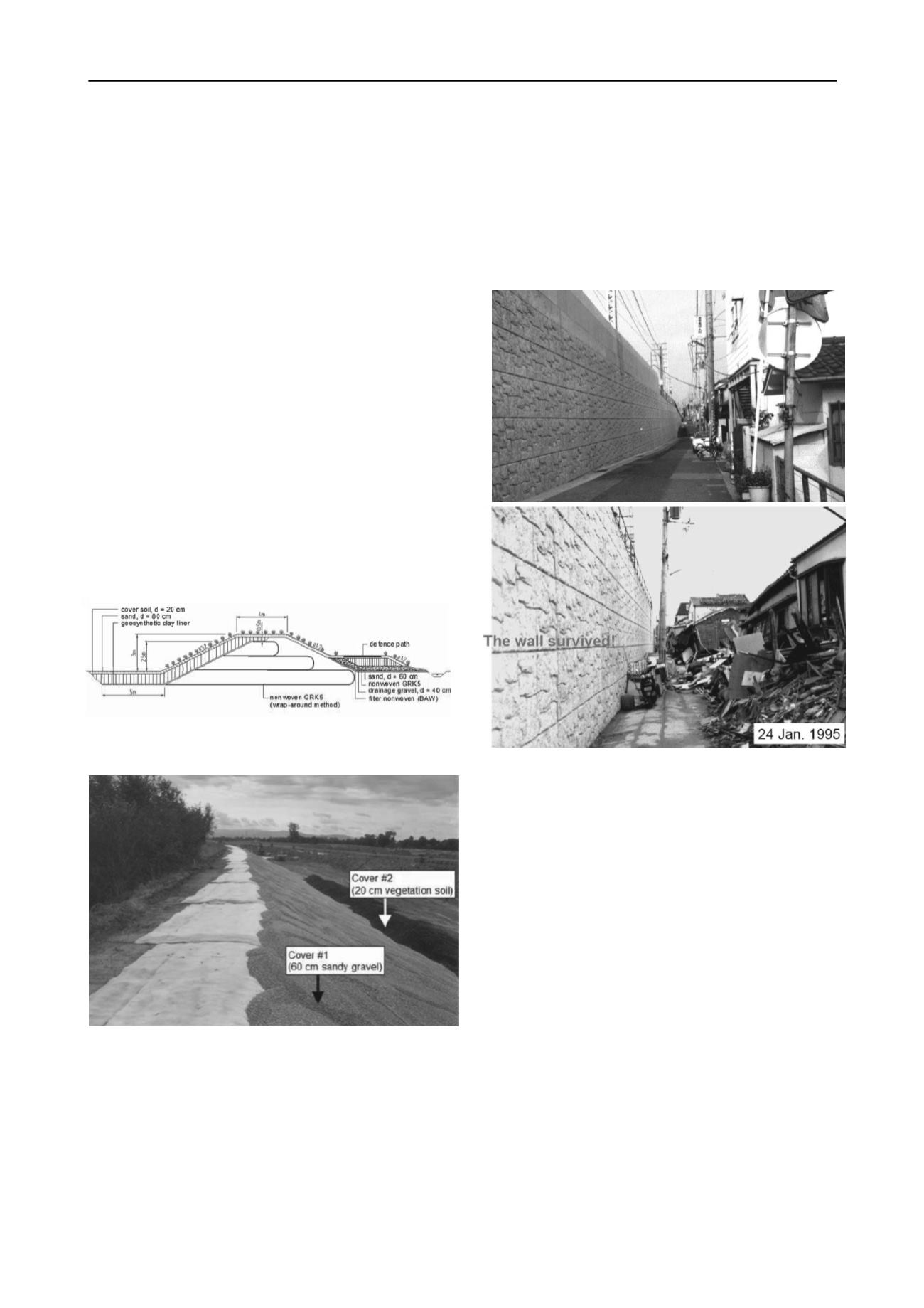
This development is based on the very positive experience
with geosynthetic reinforced soil structues under seismic
loading in Japan e.g. during the Kobe earthquake. Figure 3 is
showing a GRS structure before and after the Kobe earthquake
(Tatsuoka 2008).
Figure 3. Geosynthetic reinforced soil structure (GRS structure) as
railway embankment after completion 1992 and after the Kobe
earthquake 1995 (Tatsuoka 2008).
The synthetic polymeric materials used for soil
reinforcement applications (mainly geogrids) are thermoplastic
materials with visco-elastic material properties. The partial
safety factor for creep (A1) is often the most important
reduction factor to calculate the (long-term) design strength
(FBi,d) of a geosynthetic reinforcing element based on the
characteristic (short-term) tensile strength (FBi,K0) estimated
for a given reinforcing product by lab testing.
It has to be pointed out again and again that creep of a
synthetic reinforcing product is a product-specific visco-elastic
material response and not a deterioration or damage to the
product like e.g. corrosion for metal products. Therefore the
special product characteristics of polymeric geogrids for soil
reinforcement show that after a period of sustained loading in a
soil structure an additional spontaneous dynamic load can be
met by the original short-term tensile strength of the product.
In a new seismic design code for Japanese railway structures
this background is considered for the first time in geotechnical
engineering. NO creep reduction factor is considered to obtain
the design tensile strength of geosynthetic reinforcement under
additional seismic loading.
The NO-creep-reduction-approach for seismic loading of
geosynthetic reinforced structures (GRS) is part of the new
concepts and procedures for the recent developed design code
for Japanese railway structures reported by Tatsuoka (2009)
with the following key elements:


