1824
Proceedings of the 18
th
International Conference on Soil Mechanics and Geotechnical Engineering, Paris 2013
0.5
1
1.5
0
1
2
3
4
5
In practice this means, that safety is placed on material
properties (strength) and on actions. The recommended values
for partial factors on soils strength are
γ
φ
’
=
γ
c’
= 1.25 for
effective stress analysis and
γ
cu
= 1.4 for total stress analysis.
The largest action on slope stability comes often from the soil
weight itself. It is often considered difficult to factor soil weight
properly and thus permanent loads are, also in the Eurocodes,
left unfactored. Actions from variable loads like e.g. traffic load
are on the other hand factored. Accordingly, the recommended
values for permanent actions in EN-1997 is
γ
G
= 1.0 and for
variable actions
γ
Q
= 1.3.
According to the principles of EN1997 the overall stability
is checked by requiring that the design value of the effects of
actions E
d
driving instability is less than the design value of the
resistances R
d
, i.e. E
d
≤
R
d
. However, the common methods for
slope stability don’t usually provide these values, but rather
their ratio as an overall factor of safety. Thus an over-design
factor ODF is introduced (Frank et al.), and the requirement for
overall stability for DA 1 combination 2 and DA 3 is written as
the factor of safety calculated using design values equal to ODF
≥
1.
In short the recommended values mean that if only
effective stress parameters are used for all soil layers, and there
is no variable load, the total factor of the safety requirement is
F =
γ
φ
’
=
γ
c’
= 1.25. Similarly, if only undrained shear strength
is used and there is no variable load, the total factor of safety
requirement is F =
γ
cu
= 1.4.
Traditionally, slope stability analysis is most commonly
done applying the total safety factor approach. There is a lot of
experienced based data on total safety factors and many
engineers feel that it is easy to relate to a single safety factor. As
discussed by Leroueil et al. (1990) based on the observations by
Bourges et al (1969) a reduction of the total safety factor below
a certain limit, increases the settlements due to increasing
horizontal movements in the soil. The use of such empirical
knowledge supports the continuous use of a total safety
approach for slope stability.
The application of partial factors of safety in the Eurocodes
is indirectly implying that safety is placed were uncertainty is
found accounting also for the consequences of failure. It is the
intention to evaluate how true this implication is in relation to
slope stability and to consider what could be done to improve it.
3 RELIABILITY BASED PARTIAL SAFETY FACTORS
3.1
Introduction
In the following material partial safety factors are calculated
based on reliability theory. Firstly the theoretical bases and the
assumptions made in the calculations will be presented.
Thereafter the calculations will be done corresponding to the
present system in the Eurocodes placing safety on both the
variable action and on material properties. An alternative
calculation will then be presented where both the uncertainty
related to loads and material properties will be placed on the
material partial safety factor. In both the influence of a general
uncertainty will also be studied.
In the alternative approach, the influence of the consequence
classes into stability analysis will also be considered. As for
now, the reliability differentiation in Eurocodes is done by
applying a multiplication factor K
FI
to unfavourable loads. The
recommended values for the factor are 0.9, 1.0 and 1.1
corresponding to Reliability classes RC1, RC2 and RC3. For
slope stability problems the effect of external actions on the
stability varies from zero to rather substantial. It seems thus
rather random to apply safety related to reliability and
consequence of failure on such basis. On the other hand it is
also uncertain should the factor be applied only to variable loads
or also for permanent loads. In the latter case the problem on
how to treat ground weight arises again. However, in EN 1990
it is also stated that, quote” Reliability differentiation may also
be applied through the partial factors on resistance
γ
M
. “. The
material partial factors for the alternative approach will thus be
calculated for different target reliability index values
corresponding to the different reliability classes.
3.2
Theoretical bases
Firstly, the design point, the target reliability, the
uncertainty, load distributions and the basic parameters must be
set. The design point is set at unity and the target reliability
feasible in the reliability calculation is chosen according to EN
1990. The permanent load distribution is assumed to be normal,
the coefficient of variation equal to 0.1, the cumulative
distribution is FG(x,
µ
G
,
σ
G
) and the density distribution is
fG(x,
µ
G
,
σ
G
). For variable load a normal distribution is also
used, although Gumbel distribution might also be considered.
The distributions are FQN(x,
µ
QN
,
σ
QN
), fQN(x,
µ
QN
,
σ
QN
), 0.98
fractile is set at the design point according to one-year load. The
coefficient of variation used for the variable load is 0.4 as in EN
1990.
The material property distribution is assumed lognormal, the
cumulative distribution is FM(x,
µ
M
,
σ
M
) and the density
distribution is fM(x,
µ
M
,
σ
M
), the characteristic value is a 5 %
fractile value which is set at the design point.
When the cumulative distribution of the load is
FL(x,
µ
L
,
σ
L
), density distribution of the material property
fM(x,
µ
M
,
σ
M
), the load safety factor is
γ
L
and the material
safety factor
γ
M
, the formula for the failure probability
P
f
calculation is
1- FLx,
µ
L
,
σ
L
⋅
fMx,
µ
M
⋅γ
L
⋅γ
M
,
σ
M
⋅γ
L
⋅γ
M
∞ 0
dx=P
f
(1)
When two loads F
1
(x,
µ
1
,
σ
1
), f
1
(x,
µ
1
,
σ
1
) and F
2
(x,
µ
2
,
σ
2
),
f
2
(x,
µ
2
,
σ
2
) with items x
1,i
and x
2,i
in fractile i are combined
dependently in proportion
α
and 1-
α
,
α
is the proportion of the
load 1 in the total load, to obtain item x
1,2,i
of the combination
load in fractile i, is calculated by adding up the partial items:
µ
,,
=
µ
,
⋅
α
+
µ
,
⋅
1 −
α
(2)
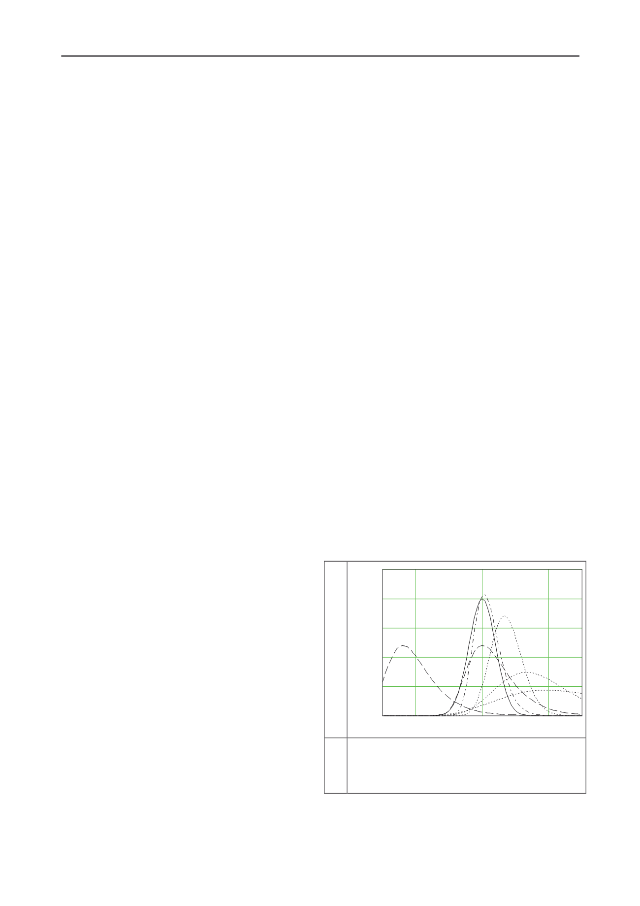
The graphs of the used distributions are presented in
Figure 1.
Probability density
Figure 1. Distributions set at the design point. Solid line:
permanent load; dashed line: variable load one-year location,
dash-dotted line: variable load in 50-year location; dotted lines:
material properties. The uncertainty distribution is equal to the
permanent load distribution but it is located at the origin.
3.3
Calculated material factors for DA3
Herein the calculations are done to resemble the present partial
safety factor approach DA3 in the Eurocodes. The loads are
combined dependently and the partial safety factors for the


