 
          1622
        
        
          Proceedings of the 18
        
        
          th
        
        
          International Conference on Soil Mechanics and Geotechnical Engineering, Paris 2013
        
        
          the principal motion. This behaviour indicated that the ground
        
        
          was not fully liquefied although the excess pore water pressure
        
        
          was generated. Similar tendency was observed in B2, the
        
        
          floating-type improvement case, and the ground in B2 was not
        
        
          also liquefied. It followed that the floating-type improvement as
        
        
          well as the fixed-type one took effect, restricting excess pore
        
        
          water pressure in a liquefiable sandy layer.
        
        
          3.3.2


            Ground settlement


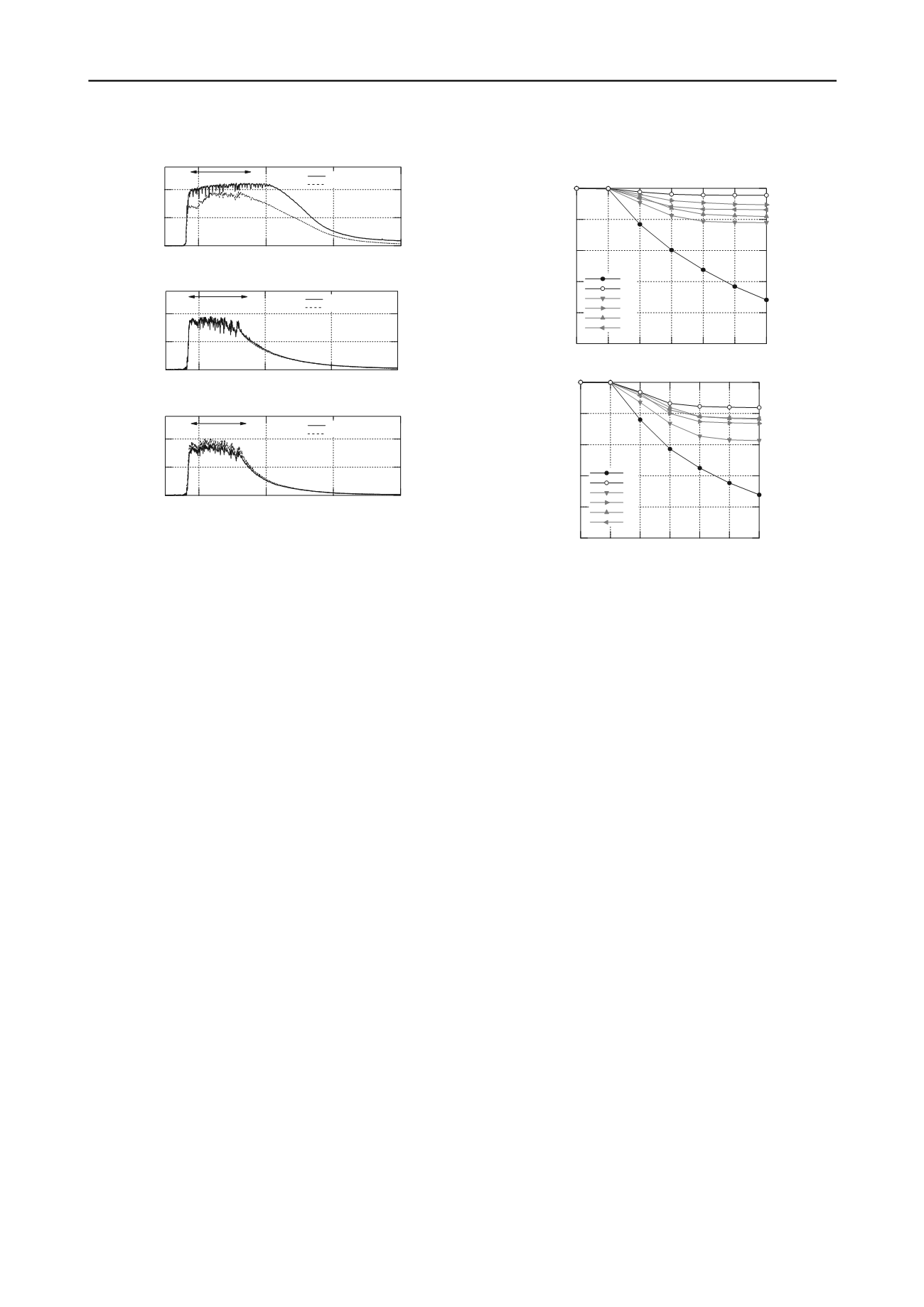
          Figure 9 presents the cumulative ground settlement in Series B
        
        
          in a proto-type scale. Each figure represents the settlement at
        
        
          the top of the lattice-shaped mold and the ground surface inside
        
        
          the grid, respectively. The horizontal axis shows the number of
        
        
          stepwise shaking.
        
        
          The ground settlement of B1, the unimprovement case,
        
        
          reached 0.23 m in Step 2 and increased every step. The final
        
        
          settlement was 0.72 m in Step 6. This large value was due to the
        
        
          liquefaction of ground in every step. In the meanwhile, the
        
        
          settlements of B2, the fixed-type improvement case, were 0.02
        
        
          m at the top of the mold and 0.06 m at the ground surface. The
        
        
          large settlement could not be found in the successive shaking
        
        
          steps due to no liquefaction.
        
        
          As for B3 ~ B6, the floating-type improvement cases, the
        
        
          settlements were a little larger than those of B2 in each shaking
        
        
          step. However, the settlements of B3 ~ B6 were much smaller
        
        
          than those of B1, and the improvement effect of the floating-
        
        
          type was confirmed in terms of ground settlement. Especially,
        
        
          the settlement of B1 increased in every step, and ones of B3 ~
        
        
          B6, meanwhile, did not increase. Therefore, the floating-type as
        
        
          well as the fixed-type was found to be effective against the
        
        
          ground settlement by liquefaction.
        
        
          4 CONCLUSIONS
        
        
          This paper examined the countermeasure effect of the floating-
        
        
          type and lattice-shaped cement treatment method by using the
        
        
          numerical analyses and the centrifuge model tests. The main
        
        
          mechanism of this method as a liquefaction countermeasure was
        
        
          that the floating-type treated soil reduced the shear stress that
        
        
          was generated in the stratum between treated soil and
        
        
          unliquefiable stratum. This effectiveness was confirmed by the
        
        
          one-dimensional numerical analyses. The centrifuge model tests
        
        
          resulted that the synchronism of the floating-type treated soil
        
        
          and the unliquefiable stratum could restrict the generation of
        
        
          excess pore water pressure the in-between stratum as well as the
        
        
          unimproved soil inside the girds. In addition, the floating-type
        
        
          improvement was found to decrease the ground settlement, and
        
        
          the improvement effect became larger by deepening the depth
        
        
          of the floating-type treated soil.
        
        
          1.0
        
        
          0.5
        
        
          0.0
        
        
          E.P.W.P.


            u/


            '


          200
        
        
          150
        
        
          100
        
        
          50
        
        
          Time (sec)
        
        
          Major strong motion
        
        
          G.L.-3.5m (Pwp1)
        
        
          G.L.-7.0m (Pwp2)
        
        
          Figure 8. Time histories of excess pore water pressure at Pwp1 and
        
        
          Pwp2: upper; unimprovement case (B1), middle; fixed-type
        
        
          improvement case (B2), floating-type improvement case (B4)
        
        
          1.0
        
        
          0.8
        
        
          0.6
        
        
          0.4
        
        
          0.2
        
        
          0.0
        
        
          Ground settlement (m)
        
        
          6 5 4 3 2 1 0
        
        
          Shaking step No.
        
        
          B1
        
        
          B2
        
        
          B3
        
        
          B4
        
        
          B5
        
        
          B6
        
        
          Figure 9. Cumulative ground settlement: upper; top of lattice-shaped
        
        
          mold at Dp1, lower; top of ground surface inside grid at Dp2
        
        
          ACKNOWLEDGEMENTS
        
        
          A part of this research was conducted within the collaborative
        
        
          project of Port and Airport Research Institute, Penta Ocean
        
        
          Construction Co., Shimizu Co., Takenaka Civil Engineering &
        
        
          Construction Co., Toa Co., Toyo Co., and Fudo Tetra Co. The
        
        
          authors are very grateful for their valuable cooperation in our
        
        
          work.
        
        
          REFERENCES
        
        
          Kitazume M. and Miyajima S. 1995. Development of PHRI Mark II
        
        
          geotechnical centrifuge.


            Technical Note of the Port and Harbour


            Research Institute


          (817), 1-33.
        
        
          Okamura M. and Inoue T. 2012. Preparation of fully saturated models
        
        
          for liquefaction study.


            International Journal of Physical Modelling


            in Geotechnics


          12(1), 39-46.
        
        
          Takahashi H., Kitazume M. and Ishibashi S. 2006a. Effect of deep
        
        
          mixing wall spacing on liquefaction mitigation.


            Proceedings of the


            International Conference on Physical Modelling in Geotechnics


          1,
        
        
          585-590.
        
        
          Takahashi H., Kitazume M., Ishibashi S. and Yamawaki S. 2006b.
        
        
          Evaluating the saturation of model ground by P-wave velocity and
        
        
          modeling of models for a liquefaction study.


            International Journal


            of Physical Modelling in Geotechnics


          6(1), 13-25.
        
        
          Takahashi H., Yamawaki S., Kitazume M. and Ishibashi S. 2006c.
        
        
          Effects of deep mixing method on liquefaction prevention and
        
        
          proposal on new arrangement of grid-type improvement.


            Report of


            the Port and Airport Research Institute


          45(2), 135-167. (in
        
        
          Japanese)